Section 5 Notice
1.Make sure that pin 1 on the user system IC socket is correctly aligned with pin 1 on the cable head before inserting the cable head into the user system IC socket.
2.The dimensions of the recommended mount pad for the user system IC socket are different from those of the MCU.
3.This user system interface cable is specifically designed for the HS2628EPI61H emulator. Do not use this cable with any other emulator station.
4.To prevent breaking of wires in the cable body, do not place heavy or sharp metal objects on the user system interface cable.
5.While the emulator station is connected to the user system with the user system interface cable, force must not be applied to the cable head. Place the emulator station, user system interface cable, and user system as shown in the example in figure 10.
Place components so that the cable body and cable head are parallel to the user system.
Emulator station | Cable |
Cable head is parallel ![]() to emulator station
to emulator station
Cable head is parallel to user system
User system
Figure 10 User System Interface Cable Location Example
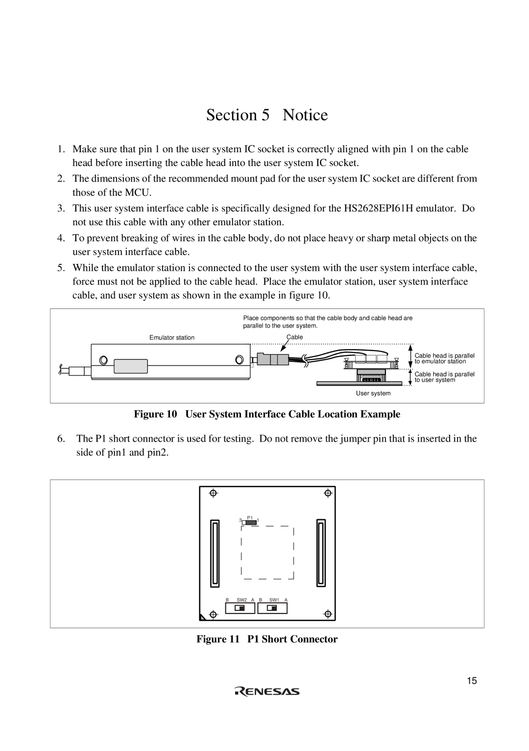
6.The P1 short connector is used for testing. Do not remove the jumper pin that is inserted in the side of pin1 and pin2.
3
P1 1
B SW2 A B SW1 A
Figure 11 P1 Short Connector
15