Manuals
/
Renesas
/
Computer Equipment
/
Server
Renesas
HEW Target
user manual
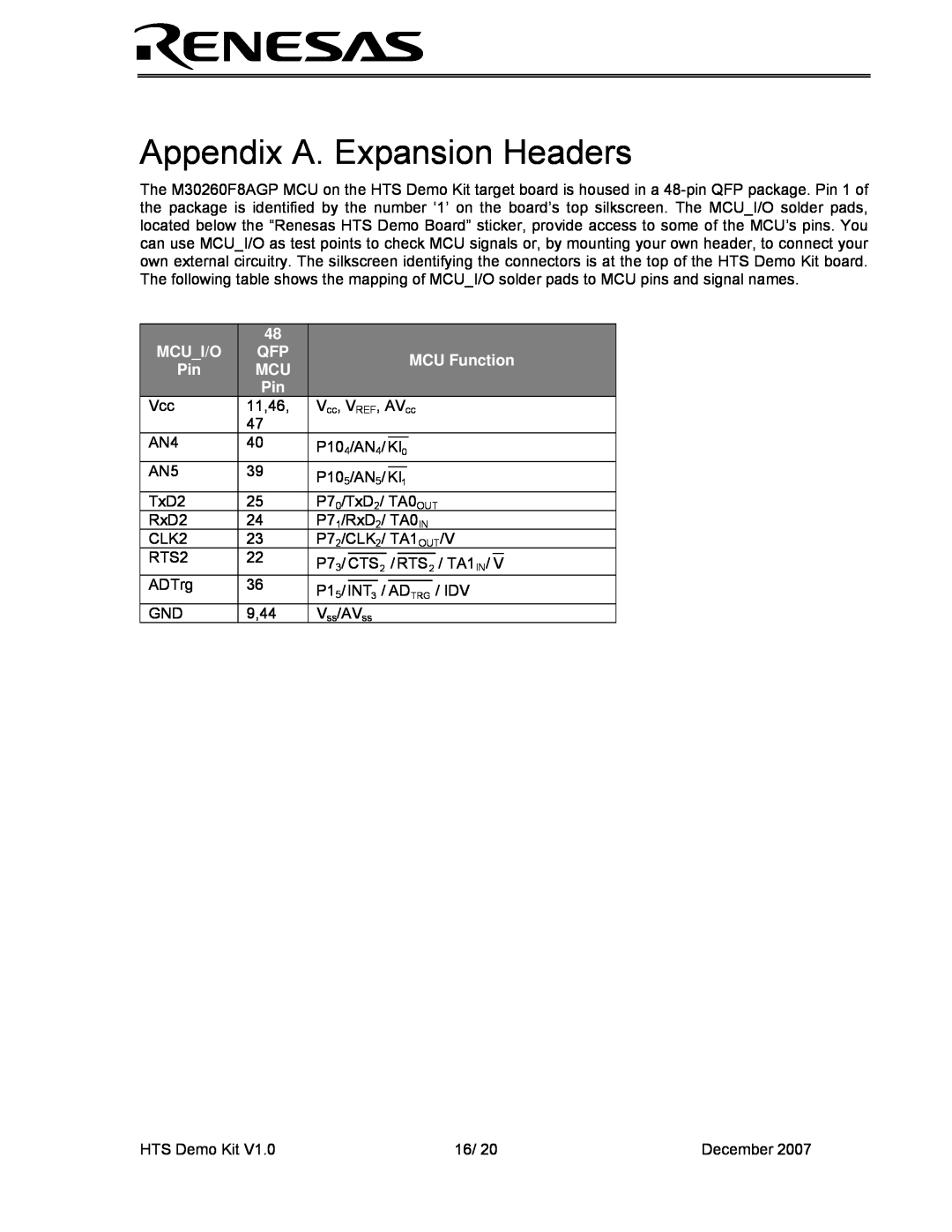
Appendix A. Expansion Headers, Mcui/O, MCU Function
Models:
HEW Target
1
16
20
20
Download
20 pages
15.68 Kb
13
14
15
16
17
18
19
20
Specs
Power Supply Requirements
Page 16
Image 16
Page 15
Page 17
Page 16
Image 16
Page 15
Page 17
Contents
HEW Target Server Demo Kit User’s Manual
Powerful Processors - Easy to Use
Rev December
HTS Demo Kit
Table of Contents
December
1.0 Preface
2.0 Introduction
1.1. Cautions
1.2. Trademarks
3.0 Contents of Product Package
3.1. HTS Demo Kit Item List
3.1.1. CD-ROM
Table 3-1 HTS Demo Kit Item List
4.0 Limited Guarantee and Support
5.0 System Connectivity
Renesas HTS Demo Board Figure 5-1 HTS Demo Kit Connectivity
5.1. Host Computer Requirements
5.2. HTS Demo Kit Board
5.3. Software Development Tools
5.3.1. HEW High-performance Embedded Workshop
6.1. HTS Demo Kit Board
6.0 Hardware
Renesas HTS Demo Board Figure 6-1 HTS Demo Kit Board
Figure 6-2 HTS Demo Kit Block Diagram
6.2. HTS Demo Kit Board Block Diagram
6.3. M16C/26A Group of MCUs
Table 7-1 System Limitations when Debugging
7.0 System Operation & Limitations
7.1. Kernel ROM Monitor Introduction
7.2. Pin and Peripheral Limitations
7.3. Memory Map
Figure 7-1 M30260F8AGP Memory Map with the Kernel Program
Kit Specification
2 The kernel transparently relocates the Reset vector to FFFD8h
7.4. Register Operation Limitations
7.6. Stop or Wait Mode Limitations
7.8. Performing Debug Using Symbols
8.0 HTS Demo Kit Board Specifications
8.1. Hardware Specifications
8.3. Power Supply Requirements
8.4. Power-Up Behavior
8.5. Operating Environment
Table 8-2 Operating and Storage Environments
Environmental Condition
Ambient Temperature
MCUI/O
Appendix A. Expansion Headers
MCU Function
Appendix B. Board Schematic & BOM
HTSdemoKitRevB.pdf HTSdemoKitBOMRevB.pdf
HTS Demo Kit
December
HTS Demo Kit
Appendix C. HTS Demo Kit Printed Circuit Board
Figure E-1 PCB Top View
Renesas HTS Demo Board
3.500 inch
Top
Page
Image
Contents