Rheem Commercial Power Direct Vent Water heater Wiring and Schematic Diagrams, 120V

Models: Commercial Power Direct Vent Water heater

1 28
Download 28 pages 32.61 Kb
Page 26
Image 26

Wiring and Schematic Diagrams

L 1

N O R M A L O P E R A T I O N S E Q U E N C E


I N D I C A T E D B Y B O X E D N U M E R A L S

L 2


2

1 2 0 V


3


B L O W E R

THERMOSTAT


AND


4

HIGH LIMIT


-


BL


Y-2


BLOWER


W


GR/YL


BK


BR -2

BR -2


BK3

TEMP

Y6

Y7


SWITCH


NC

Y-5


NC


C


C


PS2


N


PS1


PV


W-1

PV

MV

MV

GAS VALVE


LED


BL - 4


INDICATORS


BR - 3


POWER


BR - 4


THERMOSTAT


120V


IGNITION

- 3 - 4


L1

L2


PILOT VALVE

BR BR


ECO


BLACK


MAIN VALVE


SWITCH


WHITE


ON


TRANSFORMER

3


OFF


Y-


GRAY

1


W4


BK-2


GY-


Y-2


3


R-


G2

GY-5


5

1


3


-

RELAY


MV

PV/MV PV GND

GND 24V

2-GY

BL


IGNITION CONTROL


4


6


5


2


BL6


R8


R-3


BR-1


BR-3

BL-5

GY-1


BL-2


PILOT


ELECTRODE ASSY.

2 4 V

POWER

LED

IGNITION

LED

14

THERM.N.C.S.W.


THERMOSTAT LED

IGNITION

MAIN VALVELED

CONTROL

6

MGV

GND MV

24 MV/PV

5

LIMIT


PGV

PV


GND

ECO LED


PILOT VALVE


LED

5IGN.

CONNECTION DIAGRAM

SCHEMATIC

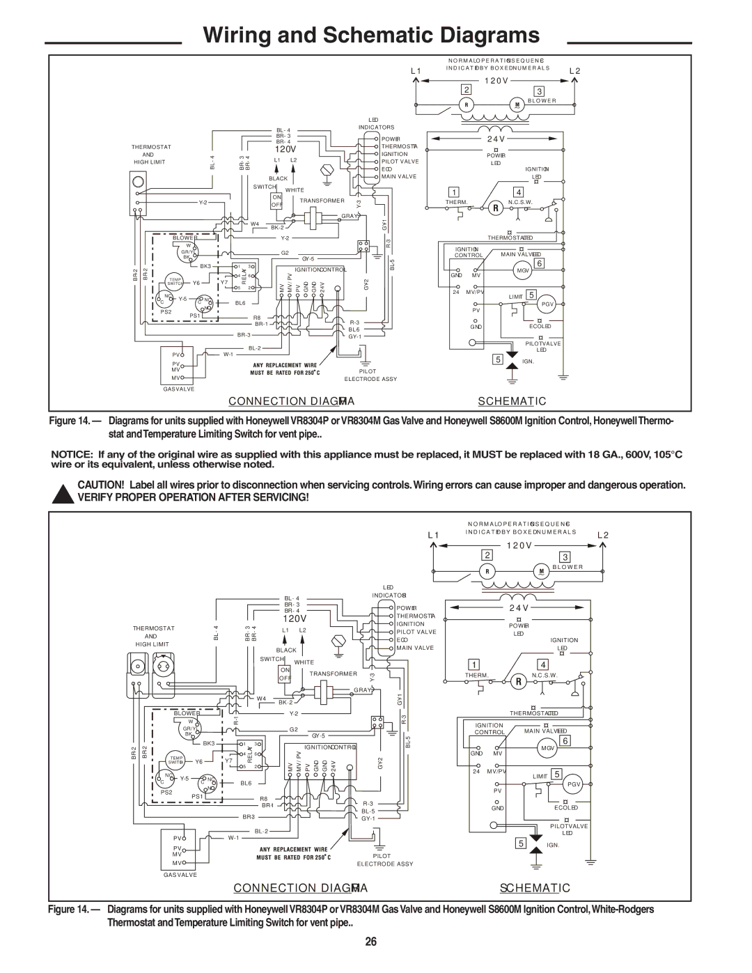
Figure 14. — Diagrams for units supplied with HoneywellVR8304P orVR8304M GasValve and Honeywell S8600M Ignition Control, HoneywellThermo- stat andTemperature Limiting Switch for vent pipe..

NOTICE: If any of the original wire as supplied with this appliance must be replaced, it MUST be replaced with 18 GA., 600V, 105°C wire or its equivalent, unless otherwise noted.

CAUTION! Label all wires prior to disconnection when servicing controls.Wiring errors can cause improper and dangerous operation.

!VERIFY PROPER OPERATION AFTER SERVICING!

L 1

N O R M A L O P E R A T I O N S E Q U E N C E


I N D I C A T E D B Y B O X E D N U M E R A L S

L 2


2

1 2 0 V


3


B L O W E R


THERMOSTAT

- 4

AND

BL

HIGH LIMIT


BLOWER


W


GR/YL


BK


BR -2

BR -2


BK3

TEMP

Y6


SWITCH


NC

Y-5

C NC


C


PS2

N

PS1


PV

PV

MV

MV

GAS VALVE


LED


BL - 4


INDICATORS


BR - 3


POWER


BR - 4


THERMOSTAT


120V


IGNITION


- 3 - 4


L1 L2


PILOT VALVE


BR BR


ECO


BLACK


MAIN VALVE


SWITCH

WHITE


ON

TRANSFORMER

3


OFF


Y-


GRAY

1


W4


BK-2


GY-


R- 1


Y-2


R- 3


G2

GY-5


5


1


3


-


RELAY


MV PV/MV PV GND GND 24V

2-GY

BL


IGNITION CONTROL


4


6


Y7


5


2


BL6


R8


R-3


BR-1


BR-3

BL-5

GY-1


BL-2

W-1


PILOT


ELECTRODE ASSY.

CONNECTION DIAGRAM


2 4 V


POWER


LED


IGNITION


LED

1

4

THERM.

N.C.S.W.


THERMOSTAT LED

IGNITION

MAIN VALVELED

CONTROL


6

GND

MV

MGV


24

MV/PV

LIMIT 5


PGV


PV


GND

ECO LED

PILOT VALVE

LED

5IGN.

SCHEMATIC

Figure 14. — Diagrams for units supplied with HoneywellVR8304P orVR8304M GasValve and Honeywell S8600M Ignition Control,White-Rodgers Thermostat andTemperature Limiting Switch for vent pipe..

26

Page 26
Image 26
Rheem Commercial Power Direct Vent Water heater installation instructions Wiring and Schematic Diagrams, 120V

Commercial Power Direct Vent Water heater specifications

The Rheem Commercial Power Direct Vent Water Heater is engineered to meet the demanding needs of commercial applications, providing reliable and efficient hot water for various business environments. With a focus on performance, efficiency, and durability, this water heater stands out in the competitive landscape of commercial water heating solutions.

One of the key features of the Rheem Commercial Power Direct Vent Water Heater is its direct vent capability. This innovative design allows for installation in confined spaces while optimizing exhaust methods. The direct vent system enables the heater to draw air from outside the building for combustion, ensuring safe operation, reducing risk of backdraft, and maintaining indoor air quality.

The water heater is powered by either natural gas or propane, accommodating diverse fuel supply preferences. With a range of storage capacities, it can cater to small and large businesses, from restaurants to industrial facilities. The product’s high recovery rate ensures that it can meet peak hot water demands, making it an ideal solution for facilities with fluctuating hot water usage.

Equipped with advanced technology, the Rheem Commercial Power Direct Vent Water Heater features a state-of-the-art electronic control system that allows for easy temperature adjustments and monitoring. This interface ensures precise temperature control, so businesses can consistently deliver hot water at the required temperatures.

Durability is a hallmark of this water heater, which incorporates premium-grade components and materials. The tank is constructed with a glass-lined steel design that enhances resistance to corrosion, while also supporting longevity. Additionally, it features robust insulation that reduces heat loss, improving energy efficiency and lowering operating costs.

Another notable characteristic is the inclusion of a high-efficiency burner that maximizes fuel utilization, promoting energy savings and reducing emissions. The heater also complies with various energy standards, making it a sustainable choice for environmentally conscious businesses.

Installation and maintenance are streamlined with the Rheem Commercial Power Direct Vent Water Heater. Its compact design and versatile venting options allow for flexible placement. Furthermore, the unit is designed for easier access to critical components, making routine service and maintenance uncomplicated.

Overall, the Rheem Commercial Power Direct Vent Water Heater represents a fusion of efficiency, ease of use, and advanced technology, making it a smart investment for commercial establishments needing reliable hot water solutions. Whether in kitchens, manufacturing plants, or commercial offices, this water heater is engineered to deliver performance and peace of mind.