Command No. |
|
|
|
|
|
|
|
| Command Descriptions |
| ||||
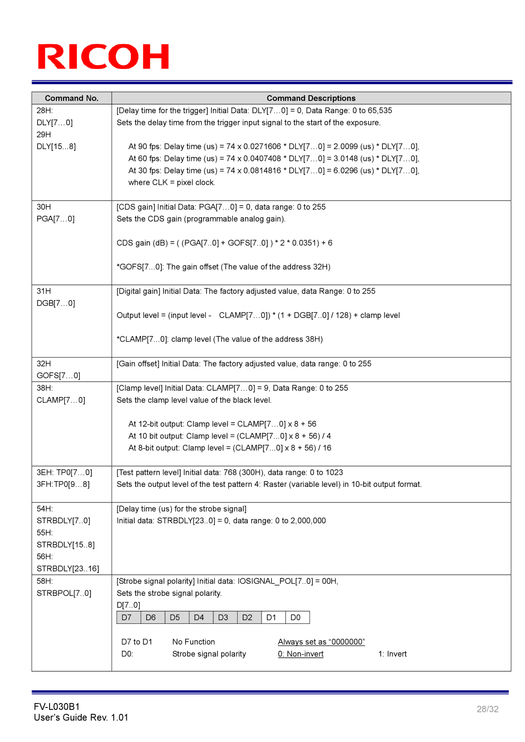
28H: |
| [Delay time for the trigger] Initial Data: DLY[70] | = 0, Data Range: 0 to 65,535 | |||||||||||
DLY[70] |
| Sets the delay time from the trigger input signal to the start of the exposure. | ||||||||||||
29H |
|
|
|
|
|
|
|
|
|
|
|
|
|
|
DLY[15...8] |
| At 90 fps: Delay time (us) = 74 x 0.0271606 * DLY[70] = 2.0099 (us) * DLY[70], | ||||||||||||
|
| At 60 fps: Delay time (us) = 74 x 0.0407408 * DLY[70] = 3.0148 (us) * DLY[70], | ||||||||||||
|
| At 30 fps: Delay time (us) = 74 x 0.0814816 * DLY[70] = 6.0296 (us) * DLY[70], | ||||||||||||
|
| where CLK = pixel clock. |
|
|
|
|
|
|
|
| ||||
|
|
|
|
|
|
|
|
|
|
|
|
| ||
30H |
| [CDS gain] Initial Data: PGA[70] = 0, data range: | 0 to 255 |
| ||||||||||
PGA[70] |
| Sets the CDS gain (programmable analog gain). |
|
|
|
| ||||||||
|
| CDS gain (dB) = ( (PGA[7..0] + GOFS[7..0] ) * 2 * 0.0351) + 6 |
| |||||||||||
|
| *GOFS[7...0]: The gain offset (The value of the address 32H) |
| |||||||||||
|
|
|
|
|
|
|
|
|
|
|
| |||
31H |
| [Digital gain] Initial Data: The factory adjusted value, data Range: 0 to 255 |
| |||||||||||
DGB[70] |
|
|
|
|
|
|
|
|
|
|
|
|
|
|
|
| Output level = (input level | CLAMP[70]) * (1 + D |
| GB[7..0] / 128) + clamp level | |||||||||
|
| *CLAMP[7...0]: clamp level (The value of the address 38H) |
| |||||||||||
|
|
|
|
|
|
|
|
|
|
|
| |||
32H |
| [Gain offset] Initial Data: The factory adjusted value, data range: 0 to 255 |
| |||||||||||
GOFS[70] |
|
|
|
|
|
|
|
|
|
|
|
|
|
|
|
|
|
|
|
|
|
|
|
|
|
|
| ||
38H: |
| [Clamp level] Initial Data: CLAMP[70] = 9, Data Ra | nge: 0 to 255 |
| ||||||||||
CLAMP[70] |
| Sets the clamp level value of the black level. |
|
|
|
| ||||||||
|
| At 12bit output: Clamp level = CLAMP[70] x 8 + 56 |
| |||||||||||
|
| At 10 bit output: Clamp level = (CLAMP[7...0] x 8 + 56) / 4 |
| |||||||||||
|
| At 8bit output: Clamp level = (CLAMP[7...0] x 8 + | 56) / 16 |
| ||||||||||
|
|
|
|
|
|
|
|
|
|
|
| |||
3EH: TP0[70] |
| [Test pattern level] Initial data: 768 (300H), data range: 0 to 1023 |
| |||||||||||
3FH:TP0[98] |
| Sets the output level of the test pattern 4: Raster (variable level) in 10bit output format. | ||||||||||||
|
|
|
|
|
|
|
|
|
|
|
|
|
| |
54H: |
| [Delay time (us) for the strobe signal] |
|
|
|
|
|
| ||||||
STRBDLY[7..0] |
| Initial data: STRBDLY[23..0] = 0, data range: 0 to 2,000,000 |
| |||||||||||
55H: |
|
|
|
|
|
|
|
|
|
|
|
|
|
|
STRBDLY[15..8] |
|
|
|
|
|
|
|
|
|
|
|
|
|
|
56H: |
|
|
|
|
|
|
|
|
|
|
|
|
|
|
STRBDLY[23..16] |
|
|
|
|
|
|
|
|
|
|
|
|
|
|
|
|
|
| |||||||||||
58H: |
| [Strobe signal polarity] Initial data: IOSIGNAL_POL[7..0] = 00H, |
| |||||||||||
STRBPOL[7..0] |
| Sets the strobe signal polarity. |
|
|
|
|
|
|
| |||||
|
| D[7..0] |
|
|
|
|
|
|
|
|
|
|
|
|
|
|
|
|
|
|
|
|
|
|
|
|
|
| |
|
| D7 | D6 | D5 | D4 |
| D3 | D2 | D1 |
| D0 |
|
| |
|
|
|
|
|
|
|
|
|
|
|
|
| ||
|
| D7 to D1 | No Function |
|
| Always set as “0000000” |
| |||||||
|
| D0: |
| Strobe signal polarity | 0: Noninvert | 1: Invert | ||||||||
|
|
|
|
|
|
|
|
|
|
|
|
|
|
|
FVL030B1 | 28/32 | |
User’s Guide Rev. 1.01 | ||
|