piece to make thinner pieces.
Resin
A sticky, sap based substance that has dried.
Ripping
A cutting operation along the length of the workpiece.
Sawblade Path
The area of the worktable or workpiece directly in line with the saw blade.
Set
The distance the tip of the sawblade tooth is bent out-
ward from the face of the blade.
Trailing End
The workpiece end last cut by the blade.
Workpiece
The item on which the cutting operation is being per- formed. The surfaces of a workpiece are commonly referred to as faces, ends, and edges.
Worktable
The surface on which the workpiece rests while perform- ing a cutting or sanding operation.
Motor Specifications and Electrical Requirements
Power Supply and Motor Specifications
![]() WARNING: To reduce the risk of electrical hazards, fire hazards or damage to the tool, use proper circuit protection. Your tool is wired at the factory for opera- tion using the voltage shown. Connect tool to a power line with the appropriate voltage and a
WARNING: To reduce the risk of electrical hazards, fire hazards or damage to the tool, use proper circuit protection. Your tool is wired at the factory for opera- tion using the voltage shown. Connect tool to a power line with the appropriate voltage and a
Follow the instructions on page 7 to connect the motor for
The
Rated Horsepower |
| 3/4 | |
|
|
| |
Voltage |
| ||
|
|
|
|
Amperes | 10 |
| 5 |
|
|
|
|
Hertz (Cycles) | 60 |
| 50/60 |
|
|
|
|
Phase |
| Single | |
|
|
| |
RPM |
| 1725 | |
|
| ||
Rotation of Shaft | Counterclockwise | ||
|
|
|
|
General Electrical Connections
DANGER: To reduce the risk of electrocution:
1.Use only identical replacement parts when servic- ing. Servicing should be performed by a qualified service technician.
2.Do not use in rain or where floor is wet.
This tool is intended for indoor residential use only.
![]() WARNING: Do not permit fingers to touch the termi- nals of plug when installing or removing the plug to or from the outlet.
WARNING: Do not permit fingers to touch the termi- nals of plug when installing or removing the plug to or from the outlet.
110-120 Volt, 60 Hz. Tool Information
The plug supplied on your tool may not fit into the outlet you are planning to use. Your local electrical code may require slightly different power cord plug connections. If these differences exist refer to and make the proper adjustments per your local code before your tool is plugged in and turned on.
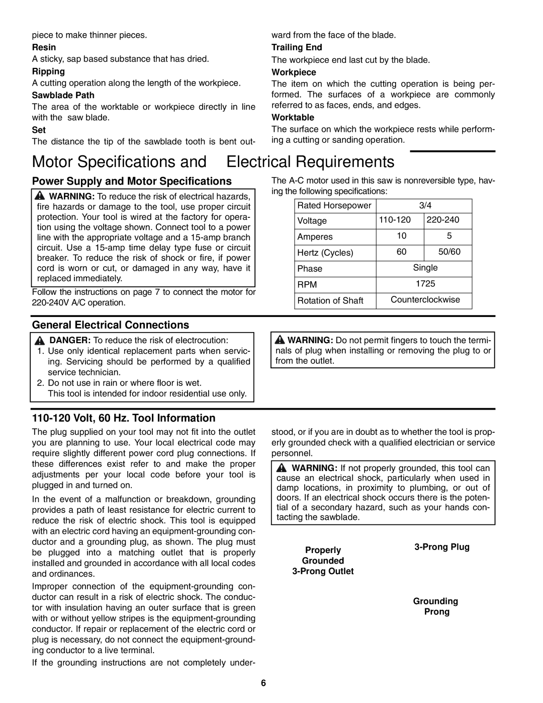
In the event of a malfunction or breakdown, grounding provides a path of least resistance for electric current to reduce the risk of electric shock. This tool is equipped with an electric cord having an
Improper connection of the
If the grounding instructions are not completely under-
stood, or if you are in doubt as to whether the tool is prop- erly grounded check with a qualified electrician or service personnel.
![]() WARNING: If not properly grounded, this tool can cause an electrical shock, particularly when used in damp locations, in proximity to plumbing, or out of doors. If an electrical shock occurs there is the poten- tial of a secondary hazard, such as your hands con- tacting the sawblade.
WARNING: If not properly grounded, this tool can cause an electrical shock, particularly when used in damp locations, in proximity to plumbing, or out of doors. If an electrical shock occurs there is the poten- tial of a secondary hazard, such as your hands con- tacting the sawblade.
Properly | |
| |
Grounded |
|
| |
| Grounding |
| Prong |
6