Changing Motor Voltage
![]() WARNING: If not properly grounded, this tool can cause an electrical shock, particularly when used in damp locations, in proximity to plumbing, or out of doors. If an electrical shock occurs there is the poten- tial of a secondary hazard, such as your hands con- tacting the knives.
WARNING: If not properly grounded, this tool can cause an electrical shock, particularly when used in damp locations, in proximity to plumbing, or out of doors. If an electrical shock occurs there is the poten- tial of a secondary hazard, such as your hands con- tacting the knives.
NOTE: The band saw is prewired at the factory for 120V operation. Use the following procedure to change motor voltage. To change to 240V application an additional wire nut is supplied from the factory. This part is included in the loose parts.
1.Unplug the band saw before making or changing any connections. Open the motor junction box cover located on the side of the motor.
2.Remove and discard the electrical tape from the wire nuts. Remove wire nuts.
3.Reconnect the leads as shown in the “Wiring Diagram” section at the rear of manual.
4.Reinstall the wire nuts and wrap with two layers of new U.L. listed electrical tape per wire nut.
5.Recheck your wiring to the wiring diagrams. Do this so you can be sure that the wiring is correct.
6.Reinstall the junction box cover.
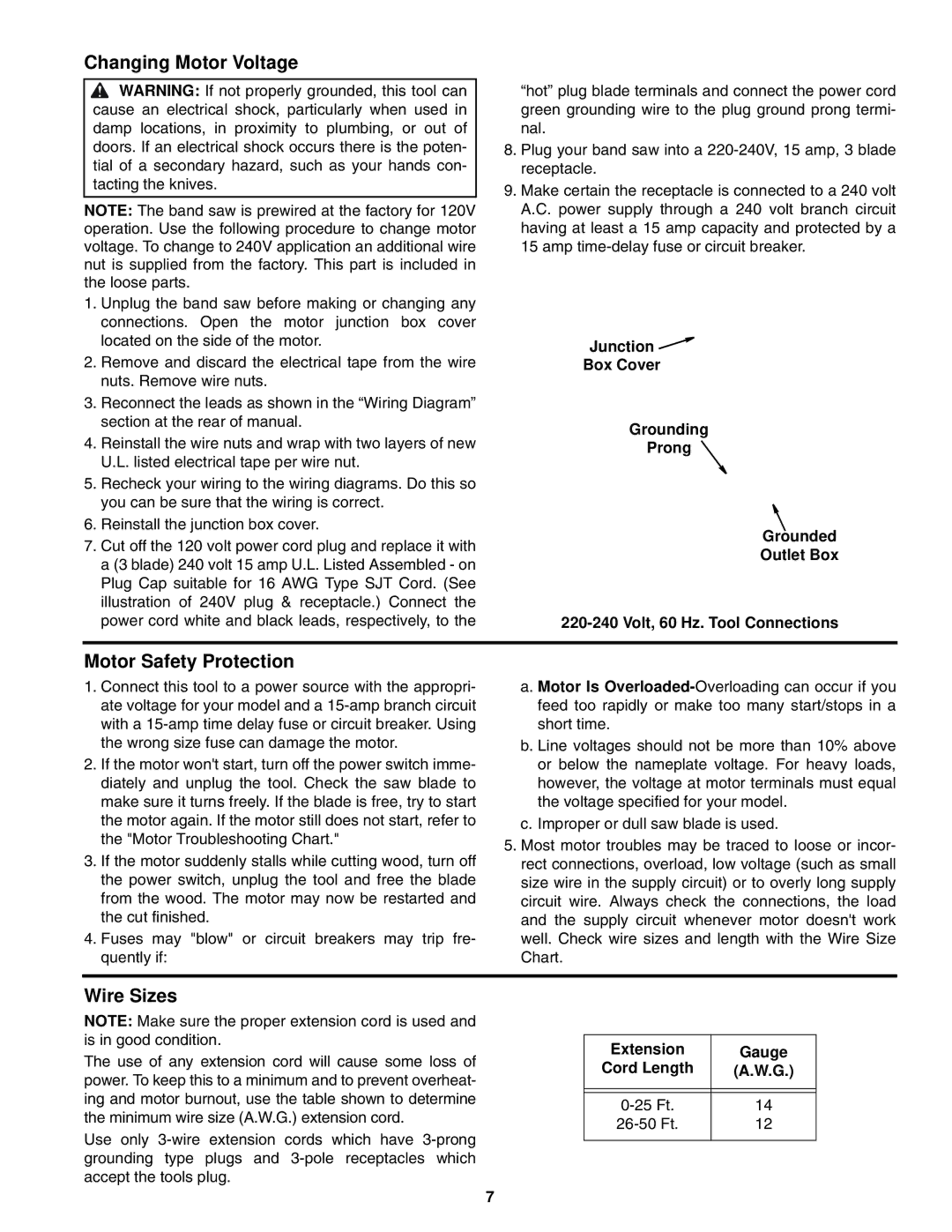
7.Cut off the 120 volt power cord plug and replace it with a (3 blade) 240 volt 15 amp U.L. Listed Assembled - on Plug Cap suitable for 16 AWG Type SJT Cord. (See illustration of 240V plug & receptacle.) Connect the power cord white and black leads, respectively, to the
“hot” plug blade terminals and connect the power cord green grounding wire to the plug ground prong termi- nal.
8.Plug your band saw into a
9.Make certain the receptacle is connected to a 240 volt A.C. power supply through a 240 volt branch circuit having at least a 15 amp capacity and protected by a 15 amp
Junction ![]()
![]()
Box Cover
Grounding
Prong
Grounded
Outlet Box
Motor Safety Protection
1.Connect this tool to a power source with the appropri- ate voltage for your model and a
2.If the motor won't start, turn off the power switch imme- diately and unplug the tool. Check the saw blade to make sure it turns freely. If the blade is free, try to start the motor again. If the motor still does not start, refer to the "Motor Troubleshooting Chart."
3.If the motor suddenly stalls while cutting wood, turn off the power switch, unplug the tool and free the blade from the wood. The motor may now be restarted and the cut finished.
4.Fuses may "blow" or circuit breakers may trip fre- quently if:
a. Motor Is
b. Line voltages should not be more than 10% above or below the nameplate voltage. For heavy loads, however, the voltage at motor terminals must equal the voltage specified for your model.
c. Improper or dull saw blade is used.
5.Most motor troubles may be traced to loose or incor- rect connections, overload, low voltage (such as small size wire in the supply circuit) or to overly long supply circuit wire. Always check the connections, the load and the supply circuit whenever motor doesn't work well. Check wire sizes and length with the Wire Size Chart.
Wire Sizes
NOTE: Make sure the proper extension cord is used and is in good condition.
The use of any extension cord will cause some loss of power. To keep this to a minimum and to prevent overheat- ing and motor burnout, use the table shown to determine the minimum wire size (A.W.G.) extension cord.
Use only
Extension | Gauge |
Cord Length | (A.W.G.) |
|
|
|
|
14 | |
12 | |
|
|
7