OPERATION
CROSS CUTTING
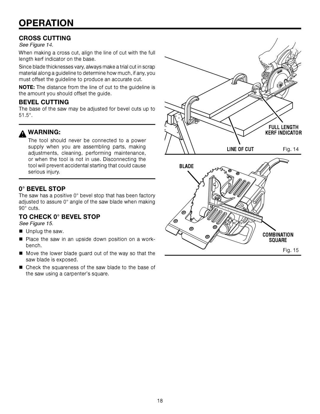
See Figure 14.
When making a cross cut, align the line of cut with the full length kerf indicator on the base.
Since blade thicknesses vary, always make a trial cut in scrap material along a guideline to determine how much, if any, you must offset the guideline to produce an accurate cut.
NOTE: The distance from the line of cut to the guideline is the amount you should offset the guide.
BEVEL CUTTING
The base of the saw may be adjusted for bevel cuts up to 51.5°.
WARNING:
The tool should never be connected to a power supply when you are assembling parts, making adjustments, cleaning, performing maintenance, or when the tool is not in use. Disconnecting the tool will prevent accidental starting that could cause serious injury.
0° BEVEL STOP
The saw has a positive 0° bevel stop that has been factory adjusted to assure 0° angle of the saw blade when making 90° cuts.
TO CHECK 0° BEVEL STOP
See Figure 15.
Unplug the saw.
Place the saw in an upside down position on a work- bench.
Move the lower blade guard out of the way so that the saw blade is exposed.
Check the squareness of the saw blade to the base of the saw using a carpenter’s square.
FULL LENGTH
KERF INDICATOR
LINE OF CUT | Fig. 14 |
|
|
BLADE
COMBINATION
SQUARE
Fig. 15
18
