ASSEMBLY
ASSEMBLING THE LOWER FOOT
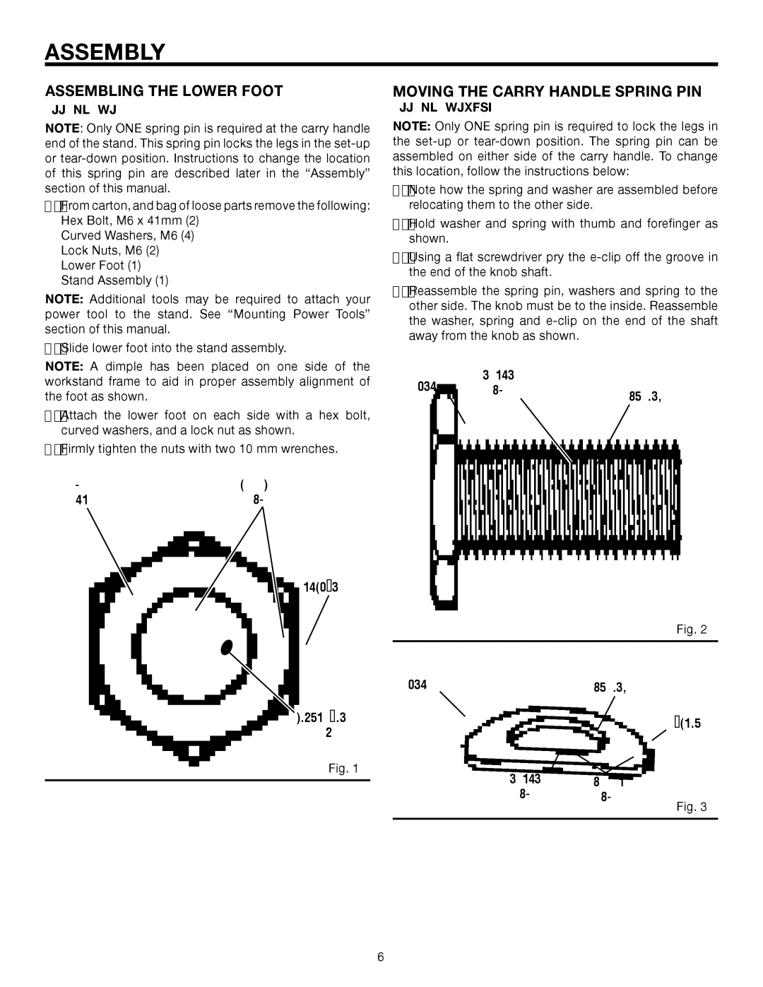
See Figure 1.
NOTE: Only ONE spring pin is required at the carry handle end of the stand. This spring pin locks the legs in the
nFrom carton, and bag of loose parts remove the following: Hex Bolt, M6 x 41mm (2)
Curved Washers, M6 (4) Lock Nuts, M6 (2) Lower Foot (1)
Stand Assembly (1)
NOTE: Additional tools may be required to attach your power tool to the stand. See “Mounting Power Tools” section of this manual.
nSlide lower foot into the stand assembly.
NOTE: A dimple has been placed on one side of the workstand frame to aid in proper assembly alignment of the foot as shown.
n Attach the lower foot on each side with a hex bolt, curved washers, and a lock nut as shown.
nFirmly tighten the nuts with two 10 mm wrenches.
HEX | CURVED |
BOLT | WASHER |
LOCK NUT
DIMPLE IN
FRAME
Fig. 1
MOVING THE CARRY HANDLE SPRING PIN
See Figures 2 and 3.
NOTE: Only ONE spring pin is required to lock the legs in the
nNote how the spring and washer are assembled before relocating them to the other side.
nHold washer and spring with thumb and forefinger as shown.
nUsing a flat screwdriver pry the
nReassemble the spring pin, washers and spring to the other side. The knob must be to the inside. Reassemble the washer, spring and
KNOB | NYLON |
|
WASHER | SPRING | |
|
|
Fig. 2
KNOB | SPRING |
NYLON STEEL
WASHER WASHER
Fig. 3
6