
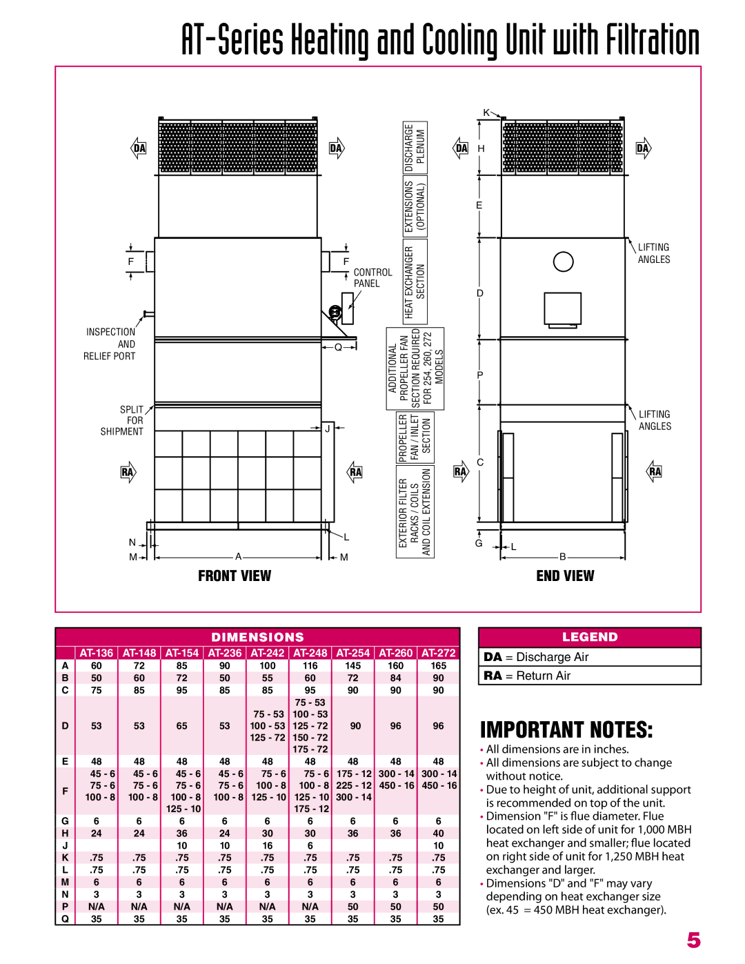
AT-248, AT-136, AT-236, AT-154, AT-148 specifications
Roberts Gorden, a prominent manufacturer in the heating and ventilation industry, offers a range of advanced infrared heating solutions designed for commercial and industrial applications. Among its diverse portfolio, the AT series, specifically the AT-148, AT-242, AT-136, AT-254, and AT-260, stands out for its efficiency and innovative features.The Roberts Gorden AT series is renowned for its advanced radiant heating technology. These heaters operate by directly warming objects and people in the space, rather than just the air. This results in lower energy consumption and enhanced comfort levels, making them ideal for large open areas such as warehouses, manufacturing facilities, and gymnasiums.
One of the key features of these models is their high thermal efficiency. The AT series is designed to offer significant energy savings compared to conventional heating methods. With efficient burner systems and reflective surfaces, these heaters can operate at high efficiency, ensuring that a greater percentage of the fuel used is converted into useful heat.
The AT-148, for instance, is known for its compact design, making it suitable for spaces with limited installation options. Despite its small size, it delivers powerful heating performance. The AT-242 and AT-254 models offer larger heating capacities, making them well-suited for expansive areas that require uniform heat distribution. The AT-260 model stands out for its ability to deliver high output even in challenging environments.
Each model in the AT series is equipped with advanced control systems, allowing for precise temperature regulation and energy management. This feature ensures that users can adapt heating output based on occupancy and specific needs, further enhancing energy efficiency.
Durability is another hallmark of the Roberts Gorden AT series. Constructed with high-quality materials, these heaters are built to withstand harsh industrial environments. Their robust design ensures a long lifespan with minimal maintenance requirements.
In summary, the Roberts Gorden AT-148, AT-242, AT-136, AT-254, and AT-260 models exemplify innovation in radiant heating technology. Featuring high efficiency, advanced control systems, and durable construction, they are engineered to provide optimal heating solutions for a variety of commercial and industrial settings. Whether for large warehouses or specialized industrial applications, the AT series offers a reliable and energy-efficient heating option.