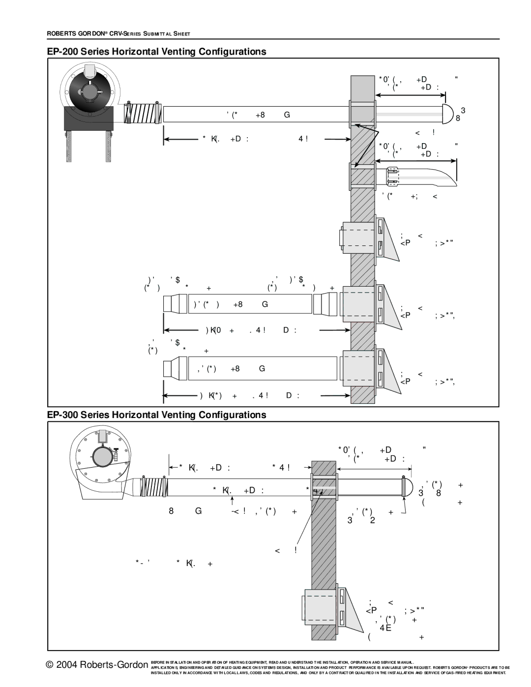
CRV-Series specifications
The Roberts Gordon CRV-Series is a revolutionary line of infrared heating systems designed to provide efficient and effective solutions for a variety of industrial and commercial applications. With an emphasis on energy efficiency, performance, and reliability, the CRV-Series stands out as a preferred choice among business owners looking to optimize their heating solutions.One of the main features of the CRV-Series is its innovative heating technology. The systems utilize infrared radiation to directly warm objects and individuals in a space, rather than heating the air. This results in faster heating times and a more comfortable environment, as it reduces heat loss and minimizes the need to overly heat the air itself. Consequently, users enjoy lower energy bills and improved comfort levels.
The CRV-Series is available in various configurations, allowing for versatility in installation and use. The modular design means that units can be easily adapted to suit different space requirements, whether in warehouses, manufacturing plants, or retail environments. This adaptability is complemented by a range of heating capacities, ensuring that businesses can find a model that fits their unique needs.
Another key characteristic of the CRV-Series is its robust construction. Built with high-quality materials, the systems are designed to withstand the rigors of industrial settings. This durability contributes to their long operational lifespan, reducing the need for frequent replacements and minimizing downtime.
Safety is also a paramount concern addressed by the CRV-Series. The systems are equipped with advanced safety features such as flame detection, automatic shut-off valves, and over-temperature protection. These features not only ensure safe operations but also provide peace of mind to users.
In terms of control and efficiency, the CRV-Series is compatible with advanced control systems that enable precise temperature regulation. This capability allows businesses to tailor their heating operations to match production schedules or occupancy levels, further enhancing energy savings.
Overall, the Roberts Gordon CRV-Series represents a blend of innovative technology, energy efficiency, and durability tailored for today's industrial and commercial environments. With its direct heating capabilities and robust features, it stands as a leading choice for businesses looking to improve their heating strategies while minimizing costs and environmental impact. Through its commitment to quality and performance, Roberts Gordon continues to set the standard in infrared heating technology with the CRV-Series.

