SYSTEM CONTROL INSTALLATION, OPERATION AND SERVICE MANUAL
2.4 Burner Electrical Ratings
CORAYVAC® burners: 120 V, 60 Hz, 1 Ø 0.3 A
VANTAGE® NP (multiburner only) burners:120 V, 60 Hz, 1 Ø 0.2 A
2.5 Outside Air Supply Blower Electrical Ratings
Outside air supply blower (P/N 90707501) has a full load rating of 1.6 A when supplied by a 120 V, 60 Hz, 1 Ø power source.
2.6Indicator Lights See Page 3, Figure 1.
1.LINE POWER, when lit, indicates power is supplied to the panel.
2.PUMP POWER 1, when, lit, indicates the relay for power to pump 1 is energized.
3.PUMP POWER 2, when, lit, indicates the relay for power to pump 2 is energized.
4.PRESSURE SWITCH 1, when lit, indicates that pressure switch 1 is closed. When blinking, indi- cates that the system is in lockout.
5.PRESSURE SWITCH 2, when lit, indicates that pressure switch 2 is closed. When blinking, indi- cates that the system is in lockout.
6.ZONE, when lit, indicates which zone relay is energized.
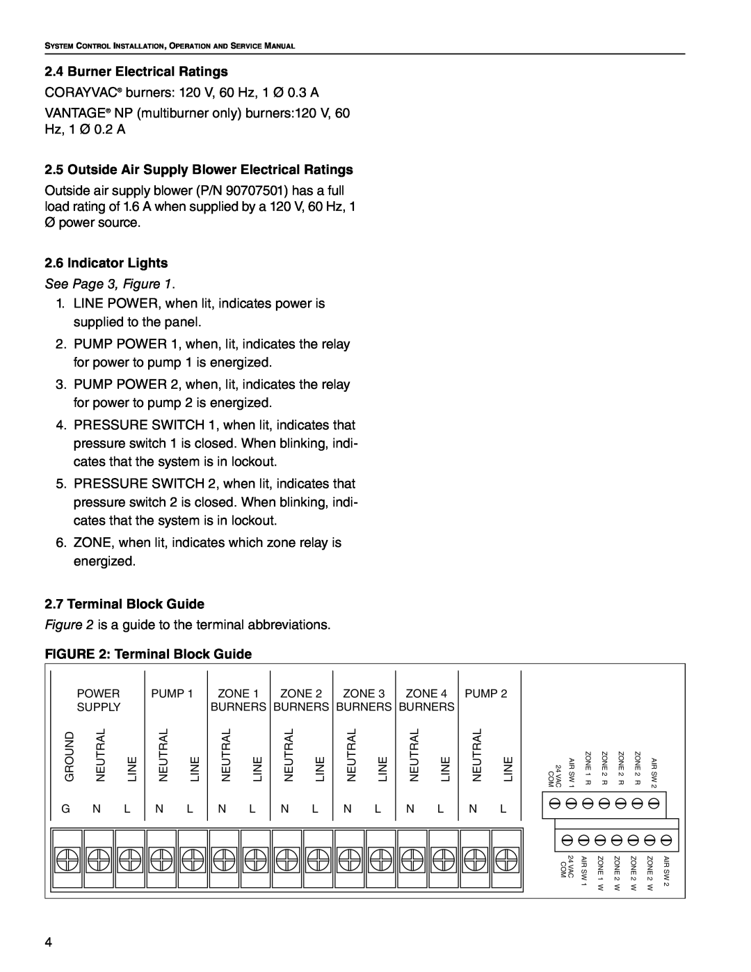
2.7Terminal Block Guide
Figure 2 is a guide to the terminal abbreviations.
FIGURE 2: Terminal Block Guide
POWER
SUPPLY
GROUND | NEUTRAL | LINE |
PUMP 1
NEUTRAL | LINE |
ZONE 1 | ZONE 2 | ||
BURNERS BURNERS | |||
NEUTRAL | LINE | NEUTRAL | LINE |
ZONE 3 | ZONE 4 | PUMP 2 | |||
BURNERS BURNERS |
|
| |||
NEUTRAL | LINE | NEUTRAL | LINE | NEUTRAL | LINE |
24 VAC COM | AIR SW 1 | ZONE 1 R | ZONE 2 R | ZONE 2 R | ZONE 2 R | AIR SW 2 |
G N L | N L | N L | N L | N L | N L | N L |
24 VAC COM | AIR SW | ZONE 1 | ZONE 2 | ZONE 2 | ZONE 2 | AIR SW |
| 1 | W | W | W | W | 2 |
4