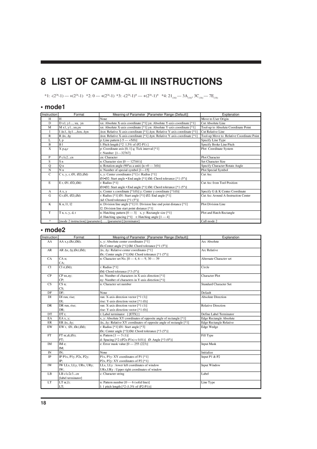
8 LIST OF CAMM-GL III INSTRUCTIONS

*1: -(226-1) — +(2 26-1) *2: 0 — +(2 26-1) *3: -(226-1)°— +(2 26-1)°*4: 21

(16)

— 3A

(16)

, 3C

— 7E

(16)


(16)


• mode1

Instruction

Format

Meaning of Parameter [Parameter Range (Default)]

Explanation

H

H

None


Move to User Origin

D

D x1, y1..., xn, yn

xn: Absolute X-axis coordinate [*1] yn: Absolute Y-axis coordinate [*1]

Cut Absolute Line

M

M x1, y1...xn,yn

xn: Absolute X-axis coordinate [*1] yn: Absolute Y-axis coordinate [*1]

Tool-up to Absolute Coordinate Point

I

I Δx1, Δy1...,Δxn, Δyn

Δxn: Relative X-axis coordinate [*1] Δyn: Relative Y-axis coordinate [*1]

Cut Relative Line

R

R Δx, Δy

Δxn: Relative X-axis coordinate [*1] Δyn: Relative Y-axis coordinate [*1]

Tool-up Move to Relative Coordinate Point

L

L p

p: Line pattern [-5 — +5(0)]


Specify Line Type

B

B l

l: Pitch length [*2 1.5% of (P2-P1) ]

Specify Broke Line Pitch

X

X p,q,r

p: Coordinate axis [0, 1] q: Tick interval [*1]

Plot Coordinate System


r: Number [1—32767]


P

P c1c2...cn

cn: Character


Plot Character

S

S n

n: Character size [0 — 127(61)]

Set Character Size

Q

Q n

n: Rotation angle (90°as a unit) [n =0 — 3(0)]

Specify Character Rotate Angle

N

N n

n: Number of special symbol [1—15]

Plot Special Symbol

C

C x, y, r, Ø1, Ø2(,Ød)

x, y: Center coordinates [*1] r: Radius [*1]

Cut Arc


Ø1•Ø2: Start angle • End angle [*1] Ød: Chord tolerance [*1 (5 °)]


E

E r, Ø1, Ø2(,Ød)

r: Radius [*1]


Cut Arc from Tool Position


Ø1•Ø2: Start angle • End angle [*1] Ød: Chord tolerance [*1 (5 °)]


A

A x, y

x: Center x coordinate [*1(0)] y: Center y coordinate [*1(0)]

Specify G & K Center Coordinate

G

G r,Ø1, Ø2(,Ød)

r: Radius [*1] Ø1: Start angle [*1] Ø2: End angle [*1]

Cut Arc Around A-Instruction Center


Δd: Chord tolerance [*1 (5°)]


K

K n, l1, l2

n: Division line angle [*1] l1: Division line end point distance [*1]

Plot Division Line


l2: Division line start point distance [*1]


T

T n, x, y, d, t

n: Hatching pattern [0 — 3]

x, y: Rectangle size [*1]

Plot and Hatch Rectangle


d: Hatching spacing [*1]

t: Hatching angle [1 — 4]


^

[mode 2 instruction] [parameter]....., [parameter] [terminator]

Call mode 2

• mode2

Instruction

Format

Meaning of Parameter [Parameter Range (Default)]

Explanation

AA

AA x,y,Øc(,Ød);

x, y: Absolute center coordinates [*1]

Arc Absolute


Øc:Center angle [*1] Ød: Chord tolerance [*1 (5 °)]


AR

AR Δx, Δy,Øc(,Ød);

Δx, Δy: Relative center coordinates [*1]

Arc Relative


Øc: Center angle [*1] Ød: Chord tolerance [*1 (5 °)]


CA

CA n;

n: Character set No. [0 — 4, 6 — 9, 30 — 39

Alternate Character set


CA;


CI

CI r(,Ød);

r: Radius [*1]

Circle


Ød: Chord tolerance [*3 (5 °)]


CP

CP nx,ny;

nx: Number of characters in X-axis direction [*1]

Character Plot


CP;

ny: Number of characters in Y-axis direction [*1]


CS

CS n;

n: Character set number

Standard Character Set


CS;


DF

DF;

None

Default

DI

DI run, rise;

run: X-axis direction vector [*1 (1)]

Absolute Direction


DI;

rise: Y-axis direction vector [*1 (0)]


DR

DR run, rise;

run: X-axis direction vector [*1 (1)]

Relative Direction


DR;

rise: Y-axis direction vector [*1 (0)]


DT

DT t;

t: Label terminator [ [ETX] ]

Define Label Terminator

EA

EA x, y;

x, y: Absolute XY coordinates of opposite angle of rectangle [*1]

Edge Rectangle Absolute

ER

ER Δx, Δy;

Δx, Δy: Relative XY coordinates of opposite angle of rectangle [*1]

Edge Rectangle Relative

EW

EW r, Ø1, Øc(,Ød);

r: Radius [*1] Ø1: Start angle [*3]

Edge Wedge


Øc: Center angle [*3] Ød: Chord tolerance [*3 (5 °)]


FT

FT n(,d(,Ø));

n: Pattern [1 — 5 (1)]

Fill Type


FT;

d: Spacing [*2 ((P2x-P1x) x 0.01)] Ø: Angle [*3 (0 °)]


IM

IM e;

e: Error mask value [0 — 255 (223)]

Input Mask


IM;


IN

IN;

None

Initialize

IP

IP P1x, P1y, P2x, P2y;

P1x, P1y: XY coordinates of P1 [*1]

Input P1 & P2


IP;

P2x, P2y: XY coordinates of P2 [*1]


IW

IW LLx, LLy, URx, URy;

LLx, LLy : lower left coordinates of window

Input Window


IW;

URx,URy : Upper right coordinates of window


LB

LB c1c2c3...cn

c: Character string

Label


[label terminator]


LT

LT n(,l);

n: Pattern number [0 — 6 (solid line)]

Line Type


LT;

l: 1 pitch length [*2 (1.5% of (P2-P1))]


18

Page 24
Image 24
Roland PNC-900 user manual List of CAMM-GL III Instructions, Mode1, Mode2

PNC-900 specifications

The Roland PNC-900 is a cutting-edge machine that has gained recognition in the world of digital printing and cutting. This multifunctional device is designed for both professional and commercial use, delivering high precision and impressive performance. With its distinctive features, the PNC-900 stands out in the marketplace, catering to various applications including signage, custom decals, and even intricate craft projects.

One of the defining characteristics of the Roland PNC-900 is its advanced cutting technology. The machine employs an optical registration system that ensures precise contour cutting. This system can detect crop marks, allowing for accuracy in cutting printed designs, which is crucial for high-quality results. The PNC-900 boasts a blade that can handle a variety of materials, from vinyl and paper to reflective materials and heat transfer film, making it versatile for different projects.

The operational speed of the PNC-900 is another attractive feature. It can deliver cutting speeds of up to 600 mm/s, significantly enhancing productivity for users who are looking to complete projects efficiently. Additionally, this model includes an articulated carriage that provides consistent cutting pressure across various media types, ensuring clean, precise lines every time.

Moreover, Roland has integrated user-friendly design into the PNC-900. The machine is equipped with a large LCD display that is easy to navigate, allowing users to access functions and settings with minimal hassle. Its intuitive interface makes it accessible even for those new to digital cutting technology.

The PNC-900 supports a range of connection options, including USB and serial connectivity, making it adaptable to most computers and design software available. This compatibility allows users to work seamlessly with their preferred graphic design programs to bring their creative visions to life.

In terms of durability, the PNC-900 is built with robust materials designed to withstand demanding conditions. Its compact design also makes it suitable for both small shops and larger production environments.

In summary, the Roland PNC-900 is a powerful and versatile cutting machine equipped with advanced technologies that ensure precise and efficient performance. Its combination of speed, precision, and ease of use makes it an appealing choice for professionals seeking reliable solutions in the digital cutting market. Whether for signage, decals, or crafts, the PNC-900 is designed to meet the high standards required by users across various industries.