3. Replacing Parts
Note: While replacing parts:
a. Make sure the power plug is unplugged from the power outlet. b. Open both side covers and rear cover.
3.1Replacing the Right Cover.
a. Take out the pressure lever (Figure 1) and four cover screws using Phillips screw driver (Figure 2).
Figure 1
Figure
b. Pull out the male control panel connector from the
Figure
3.2Replacing the Sub-PCB
a. Refer to “Replacing Right Cover”.
c. Loosen two screws from
Figure
d. Follow the reverse order to assemble the Right Cover back.
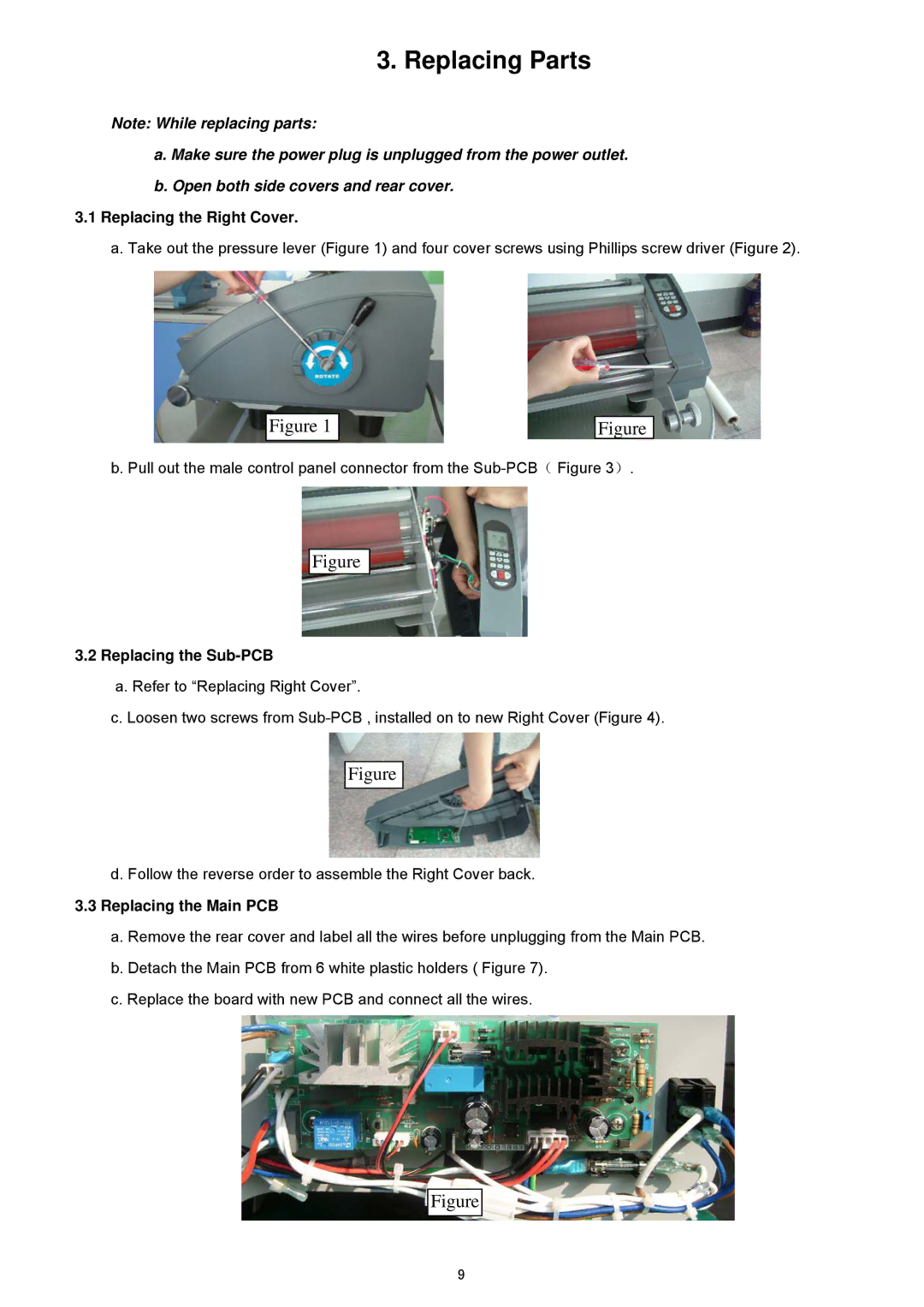
3.3Replacing the Main PCB
a.Remove the rear cover and label all the wires before unplugging from the Main PCB.
b.Detach the Main PCB from 6 white plastic holders ( Figure 7).
c.Replace the board with new PCB and connect all the wires.
Figure
9