Manuals
/
Rugged Outback
/
Computer Equipment
/
Switch
Rugged Outback
RS416
manual
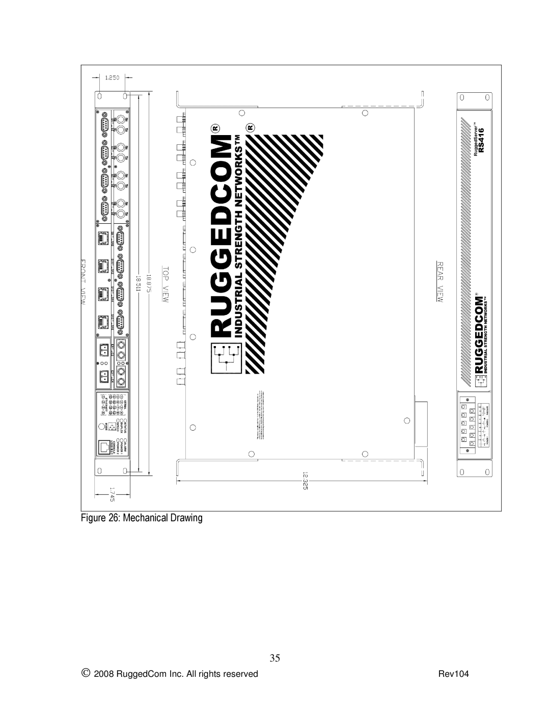
Mechanical Drawing
Models:
RS416
1
35
36
36
Download
36 pages
56.83 Kb
29
30
31
32
33
34
35
36
Specifications
Install
Failsafe Alarm Relay Wiring
Warranty
Power source is AC
Feature Highlights
Mode Colour
Page 35
Image 35
Figure 26: Mechanical Drawing
35
2008 RuggedCom Inc. All rights reserved
Rev104
Page 34
Page 36
Page 35
Image 35
Page 34
Page 36
Contents
RuggedServer RS416
Trademarks
Table of Contents
Table of Tables
Table of Figures
2008 RuggedCom Inc. All rights reserved Rev104
Functional Overview
Feature Highlights
Product Overview
2008 RuggedCom Inc. All rights reserved Rev104
Colour Description
Display Panel Description
LEDs Green Solid Link
Mode Colour
Mounting
Installation
19 Rack Mount Adapters
Rack Mounting
Panel and DIN Rail Mounting
RS416 Series PANEL/DIN Rail mounting diagram with
RS416 Series Philips Screw Terminal Block
Power Supply Wiring and Grounding
PS1 Live / +
Power source is AC
Chassis Ground is connected to the Safety Ground
Description Usage
AC Power Supply Wiring Examples
Must be installed and separately identified
DC Power Supply Wiring Examples
DC Power supply wiring examples
Installed within 3m of unit
Dual Power Supplies Wiring Examples
Dielectric Strength Hipot Testing
Dielectric Strength Hipot Testing
Failsafe Alarm Relay Wiring
Failsafe Alarm Relay Wiring
RS232 over RJ45 console cable pin-out Male RJ45
Console Port Wiring
Fiber Serial Interface
Serial Ports
DB9 Female DCE Port pin-out
2 RS232/RS485/RS422 via DB9
RJ45 Port pin-out No internal termination is provided
3 RS232/RS485/RS422 via RJ45
Shield
Conceptual recommended RS485 wiring diagram
4 RS485 Wiring
Serial Port Transient Protection
+Rx +Tx No Connection
Ethernet Ports
Copper Ports
Fiber Optic Ports
100FX LC connector 100FX SC connector
Ethernet panel LED description
Ethernet Panel Description
Failsafe Relay Contact Ratings
Technical Specifications
Power Supply Specifications
Serial Ports
Data Port Specifications
Ethernet Ports
2008 RuggedCom Inc. All rights reserved Rev104
95%
Type Test Specifications
Electrical Safety Levels Comments
Type Test Specification Atmospheric Environment
Operating Environment
Mechanical Specifications
Mechanical Drawing
FCC Part 15, Class a Approved
Warranty
Agency Approvals
Agency Standards Comments
Top
Page
Image
Contents