REAR PANEL CONNECTIONS
ZONE | CONNECTING THE INFRARED COMPONENTS |
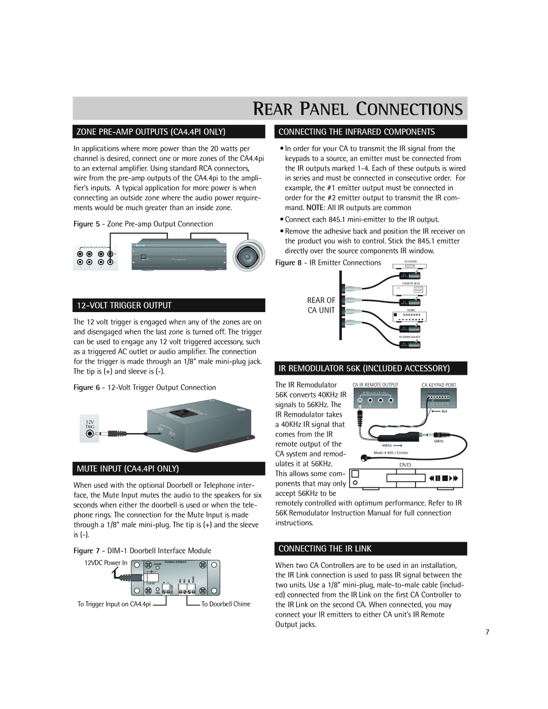
In applications where more power than the 20 watts per channel is desired, connect one or more zones of the CA4.4pi to an external amplifier. Using standard RCA connectors, wire from the
Figure 5 - Zone Pre-amp Output Connection
ZONE PREAMP OUTPUTS
R
L
4 | 3 | 2 | 1 |
12-VOLT TRIGGER OUTPUT
The 12 volt trigger is engaged when any of the zones are on and disengaged when the last zone is turned off. The trigger can be used to engage any 12 volt triggered accessory, such as a triggered AC outlet or audio amplifier. The connection for the trigger is made through an 1/8” male
Figure 6 - 12-Volt Trigger Output Connection
12V TRIG
MUTE INPUT (CA4.4PI ONLY)
When used with the optional Doorbell or Telephone inter- face, the Mute Input mutes the audio to the speakers for six seconds when either the doorbell is used or when the tele- phone rings. The connection for the Mute Input is made through a 1/8” male
Figure 7 - DIM-1 Doorbell Interface Module
12VDC Power In | POWER |
| DOORBELL INTERFACE |
+12V DC | DB3 | DB2 | DB1 | TRANS |
TRIG OUT |
|
|
| |
TRIG |
|
|
| |
To Trigger Input on CA4.4pi |
|
|
| To Doorbell Chime |
•In order for your CA to transmit the IR signal from the keypads to a source, an emitter must be connected from the IR outputs marked
•Connect each 845.1 mini-emitter to the IR output.
•Remove the adhesive back and position the IR receiver on the product you wish to control. Stick the 845.1 emitter directly over the source components IR window.
Figure 8 - IR Emitter Connections | CD PLAYER |
| 845 |
| EMITTER |
| CASSETTE DECK |
REAR OF | EMITTER |
CA UNIT | 845 |
TUNER | |
| 845 |
| EMITTER |
| TO OTHER SOURCE |
| 845 |
| EMITTER |
IR REMODULATOR 56K (INCLUDED ACCESSORY)
The IR Remodulator | CA IR REMOTE OUTPUT | CA KEYPAD PORT | |||
56K converts 40KHz IR |
| IR REMOTE OUTPUT |
| ||
|
|
|
|
| |
signals to 56KHz. The | 4 | 3 | 2 | 1 | 1 2 3 4 5 6 7 8 |
|
|
|
| Red | |
IR Remodulator takes |
|
|
|
| |
|
|
|
|
| |
a 40KHz IR signal that |
|
|
|
|
|
comes from the IR |
|
|
|
|
|
remote output of the |
|
|
| 40KHz | 56KHz |
|
|
|
| ||
CA system and remod- |
|
| Model # 845.1 Emitter |
| |
|
|
|
|
| |
ulates it at 56KHz. |
|
|
| DVD |
|
This allows some com- |
|
|
|
|
|
ponents that may only |
|
|
|
|
|
accept 56KHz to be |
|
|
|
|
|
remotely controlled with optimum performance. Refer to IR 56K Remodulator Instruction Manual for full connection instructions.
CONNECTING THE IR LINK
When two CA Controllers are to be used in an installation, the IR Link connection is used to pass IR signal between the two units. Use a 1/8”
7