Manuals
/
Ryobi
/
Lawn and Garden
/
Trimmer
Ryobi
890r
manual
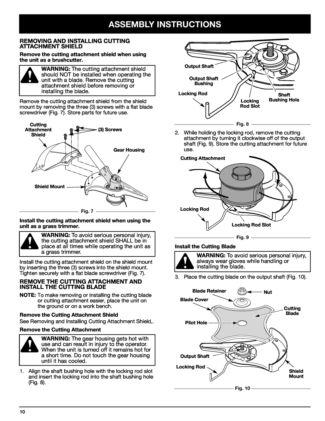
Removing And Installing Cutting Attachment Shield, Assembly Instructions
Models:
890r
1
10
30
30
Download
30 pages
42.82 Kb
7
8
9
10
11
12
13
14
Troubleshooting
Specs
Install
Symbol Meaning
Warranty
Maintenance
Accessories/Replacement Parts
Adjusting Trimming Line Length
Cleaning the Air Filter
Replacement Parts
Page 10
Image 10
Page 9
Page 11
Page 10
Image 10
Page 9
Page 11
Contents
OPERATOR’S MANUAL
IMPORTANT MANUAL
FOR QUESTIONS, CALL 1-800-345-8746 in U.S. or
890r 4-Cycle Gas Trimmer/Brushcutter
SERVICE INFORMATION
TABLE OF CONTENTS
PRODUCT REFERENCES, ILLUSTRATIONS AND SPECIFICATIONS
INTRODUCTION
California Proposition 65 Warning
CALIFORNIA EMISSION REGULATIONS
SPARK ARRESTOR
THE ENGINE EXHAUST FROM THIS PRODUCT CONTAINS CHEMICALS
SAFETY WARNINGS FOR GAS TRIMMERS
IMPORTANT SAFETY INFORMATION
SYMBOL MEANING
RULES FOR SAFE OPERATION
WHILE OPERATING WITH CUTTING BLADE
AFTER USE
SYMBOLMEANING SAFETY ALERT SYMBOL
OTHER SAFETY WARNINGS
SAFETY AND INTERNATIONAL SYMBOLS
FOR SERVICE INFORMATION, CALL
THROWN OBJECTS AND ROTATING CUTTER CAN CAUSE SEVERE INJURY
SYMBOLMEANING OIL
TRIMMER/BRUSHCUTTER SAFETY
ON/OFF STOP CONTROL
KNOW YOUR UNIT
APPLICATIONS
INSTALLING AND ADJUSTING THE J-HANDLE
ASSEMBLY INSTRUCTIONS
INSTALLING THE HARNESS
Install the Cutting Blade
REMOVING AND INSTALLING CUTTING ATTACHMENT SHIELD
REMOVE THE CUTTING ATTACHMENT AND INSTALL THE CUTTING BLADE
Remove the Cutting Attachment Shield
REMOVE THE CUTTING BLADE AND INSTALL THE CUTTING ATTACHMENT
Remove the Cutting Blade
Install the Cutting Attachment
OIL AND FUEL INFORMATION
RECOMMENDED OIL TYPE
ADDING OIL TO CRANKCASE - INITIAL USE
Using Blended Fuels
FUELING UNIT
RECOMMENDED FUEL TYPE
Using Fuel Additives
STARTING/STOPPING INSTRUCTIONS
STARTING INSTRUCTIONS
OPERATING THE CLICK-LINK SYSTEM
OPERATING INSTRUCTIONS
STOPPING INSTRUCTIONS
Installing the Cutting Attachment or Add-Ons
HOLDING THE TRIMMER
ADJUSTING TRIMMING LINE LENGTH
TIPS FOR BEST TRIMMING RESULTS
DECORATIVE TRIMMING
USING THE CUTTING BLADE
Cutting Blade Operating Tips
MAINTENANCE REQUIRED
MAINTENANCE AND REPAIR INSTRUCTIONS
MAINTENANCE SCHEDULE
LINE INSTALLATION
INSTALLING A PREWOUND REEL
Replacement Parts
CHANGING THE OIL
CHECKING THE OIL LEVEL
CAUTION Wear gloves to prevent injury when handling the unit
AIR FILTER MAINTENANCE
Cleaning the Air Filter
Clean Air Filter
CARBURETOR ADJUSTMENT
ROCKER ARM CLEARANCE
Adjust Idle Speed Screw
3. Remove the screw on back of the engine cover Fig
ACCESSORIES/REPLACEMENT PARTS
SPARK ARRESTOR MAINTENANCE
REPLACING THE SPARK PLUG
STORAGE
CLEANING AND STORAGE
CLEANING
LONG TERM STORAGE
ENGINE WILL NOT START
TROUBLESHOOTING
ENGINE LACKS POWER OR STALLS WHEN CUTTING
ENGINE WILL NOT IDLE
ENGINE
SPECIFICATIONS
DRIVE SHAFT & CUTTING ATTACHMENT
Page
OWNERS WARRANTY RESPONSIBILITIES
CALIFORNIA EMISSION CONTROL WARRANTY STATEMENT
YOUR WARRANTY RIGHTS AND OBLIGATIONS
MANUFACTURERS WARRANTY COVERAGE
RYOBI OUTDOOR PRODUCTS
LIMITED TWO-YEAR WARRANTY
SAVE THESE INSTRUCTIONS FOR FUTURE REFERENCE
RYOBI CANADA INC
Top
Page
Image
Contents