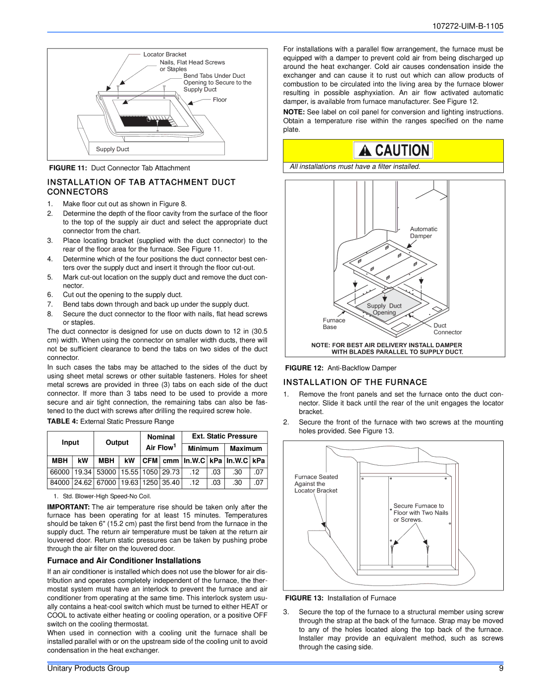
Locator Bracket
Nails, Flat Head Screws or Staples
Bend Tabs Under Duct Opening to Secure to the Supply Duct
![]() Floor
Floor
Supply Duct
FIGURE 11: Duct Connector Tab Attachment
INSTALLATION OF TAB ATTACHMENT DUCT CONNECTORS
1.Make floor cut out as shown in Figure 8.
2.Determine the depth of the floor cavity from the surface of the floor to the top of the supply air duct and select the appropriate duct connector from the chart.
3.Place locating bracket (supplied with the duct connector) to the rear of the floor area for the furnace. See Figure 11.
4.Determine which of the four positions the duct connector best cen- ters over the supply duct and insert it through the floor
5.Mark
6.Cut out the opening to the supply duct.
7.Bend tabs down through and back up under the supply duct.
8.Secure the duct connector to the floor with nails, flat head screws or staples.
The duct connector is designed for use on ducts down to 12 in (30.5 cm) width. When using the connector on smaller width ducts, there will not be sufficient clearance to bend the tabs on two sides of the duct connector.
In such cases the tabs may be attached to the sides of the duct by using sheet metal screws or other suitable fasteners. Holes for sheet metal screws are provided in three (3) tabs on each side of the duct connector. If more than 3 tabs need to be used to provide a more secure and air tight connection, the remaining tabs can also be fas- tened to the duct with screws after drilling the required screw hole.
TABLE 4: External Static Pressure Range
Input | Output | Nominal | Ext. Static Pressure | |||||||
Air Flow1 |
|
|
|
| ||||||
Minimum | Maximum | |||||||||
|
|
|
| |||||||
MBH | kW | MBH | kW | CFM | cmm | In.W.C | kPa | In.W.C | kPa | |
|
|
|
|
|
|
|
|
|
| |
66000 | 19.34 | 53000 | 15.55 | 1050 | 29.73 | .12 | .03 | .30 | .07 | |
84000 | 24.62 | 67000 | 19.63 | 1250 | 35.40 | .12 | .03 | .30 | .07 | |
1. Std.
IMPORTANT: The air temperature rise should be taken only after the furnace has been operating for at least 15 minutes. Temperatures should be taken 6" (15.2 cm) past the first bend from the furnace in the supply duct. The return air temperature must be taken at the return air louvered door. Return static pressures can be taken by pushing probe through the air filter on the louvered door.
Furnace and Air Conditioner Installations
If an air conditioner is installed which does not use the blower for air dis- tribution and operates completely independent of the furnace, the ther- mostat system must have an interlock to prevent the furnace and air conditioner from operating at the same time. This interlock system usu- ally contains a
When used in connection with a cooling unit the furnace shall be installed parallel with or on the upstream side of the cooling unit to avoid condensation in the heat exchanger.
For installations with a parallel flow arrangement, the furnace must be equipped with a damper to prevent cold air from being discharged up around the heat exchanger. Cold air causes condensation inside the exchanger and can cause it to rust out which can allow products of combustion to be circulated into the living area by the furnace blower resulting in possible asphyxiation. An air flow activated automatic damper, is available from furnace manufacturer. See Figure 12.
NOTE: See label on coil panel for conversion and lighting instructions. Obtain a temperature rise within the ranges specified on the name plate.
All installations must have a filter installed.
Automatic
Damper
Supply Duct
Opening
Furnace
BaseDuct
Connector
NOTE: FOR BEST AIR DELIVERY INSTALL DAMPER
WITH BLADES PARALLEL TO SUPPLY DUCT.
FIGURE 12: Anti-Backflow Damper
INSTALLATION OF THE FURNACE
1.Remove the front panels and set the furnace onto the duct con- nector. Slide it back until the rear of the unit engages the locator bracket.
2.Secure the front of the furnace with two screws at the mounting holes provided. See Figure 13.
Furnace Seated
Against the
Locator Bracket
Secure Furnace to Floor with Two Nails or Screws.
FIGURE 13: Installation of Furnace
3.Secure the top of the furnace to a structural member using screw through the strap at the back of the furnace. Strap may be moved to any of the holes located along the top back of the furnace. Installer may provide an equivalent method, such as screws through the casing side.
Unitary Products Group | 9 |