IGNITION SYSTEM SEQUENCE
1.Turn the oil supply ON at external valve on the oil pump, and/or at the oil tank.
2.Set the thermostat above room temperature to call for heat.
3.System
a.The burner motor will start and come up to speed.
b.Shortly after the burner motor
c.The solenoid valve on the oil pump will open providing oil flow to the nozzle.
d.The oil vapor will ignite. The cad cell flame detector will detect the flame. The resistance will drop below 1600 ohms.
e.After flame is established, the supply air blower will start when the fan switch reaches approximately 110° F (43.3° C).
f.After flame is extinguished, the supply air blower will continue to operate until the air temperature at the fan switch is below 90o F (32.2o C).
FIRE OR EXPLOSION HAZARD
Failure to follow the safety warnings exactly could result in serious injury, death or property damage.
Pressing the reset button repeatedly could cause a pool of oil to form in the bottom of the chamber. If ignited, could result in a very dangerous situation which could result in personal injury, property damage, and/or death.
IMPORTANT: Burner ignition may not be satisfactory on first
The furnace should have a safety or fire
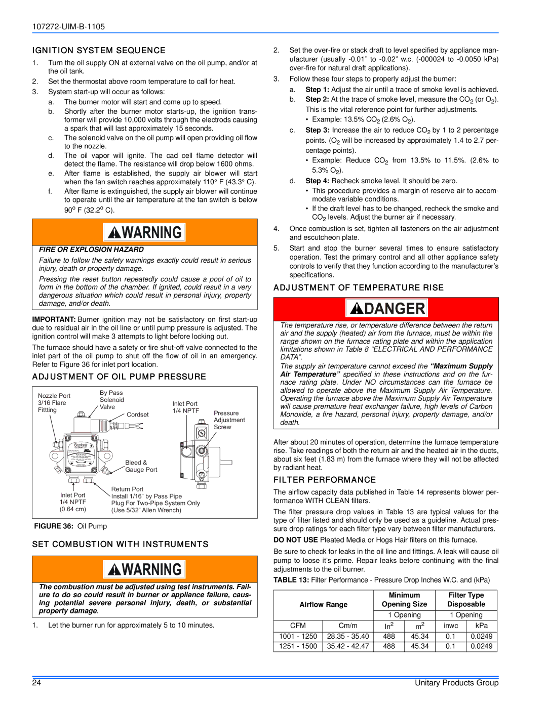
ADJUSTMENT OF OIL PUMP PRESSURE
Nozzle Port |
| By Pass |
|
|
| Solenoid |
|
| |
3/16 Flare |
| Inlet Port |
| |
| Valve |
| ||
Fittting |
| 1/4 NPTF |
| |
| Cordset | Pressure | ||
|
|
| ||
|
|
| Adjustment | |
|
|
|
| |
|
|
|
| Screw |
Beckett |
|
|
|
|
CLEANCUT | INLET |
|
|
|
USE ONLY WITH |
|
|
|
|
VALVE ON DELAY |
|
|
|
|
|
|
|
| |
4 GPH |
|
|
| |
NO. 2 & LIGHTER FUEL |
|
|
| |
3 GPH |
|
|
| |
NO. 2 FUEL |
| Bleed & |
|
|
INLET |
|
| ||
Made by Suntec |
|
|
| |
Exclusively for Beckett |
|
|
| |
|
| Gauge Port |
|
|
|
| Return Port |
|
|
Inlet Port |
| Install 1/16” by Pass Pipe |
| |
1/4 NPTF |
| Plug For |
| |
(0.64 cm) |
| (Use 5/32” Allen Wrench) |
| |
FIGURE 36: Oil Pump
SET COMBUSTION WITH INSTRUMENTS
The combustion must be adjusted using test instruments. Fail- ure to do so could result in burner or appliance failure, caus- ing potential severe personal injury, death, or substantial property damage.
1.Let the burner run for approximately 5 to 10 minutes.
2.Set the
3.Follow these four steps to properly adjust the burner:
a.Step 1: Adjust the air until a trace of smoke level is achieved.
b.Step 2: At the trace of smoke level, measure the CO2 (or O2). This is the vital reference point for further adjustments.
•Example: 13.5% CO2 (2.6% O2).
c.Step 3: Increase the air to reduce CO2 by 1 to 2 percentage points. (O2 will be increased by approximately 1.4 to 2.7 per- centage points).
•Example: Reduce CO2 from 13.5% to 11.5%. (2.6% to 5.3% O2).
d.Step 4: Recheck smoke level. It should be zero.
•This procedure provides a margin of reserve air to accom- modate variable conditions.
•If the draft level has to be changed, recheck the smoke and CO2 levels. Adjust the burner air if necessary.
4.Once combustion is set, tighten all fasteners on the air adjustment and escutcheon plate.
5.Start and stop the burner several times to ensure satisfactory operation. Test the primary control and all other appliance safety controls to verify that they function according to the manufacturer’s specifications.
ADJUSTMENT OF TEMPERATURE RISE
The temperature rise, or temperature difference between the return air and the supply (heated) air from the furnace, must be within the range shown on the furnace rating plate and within the application limitations shown in Table 8 “ELECTRICAL AND PERFORMANCE DATA”.
The supply air temperature cannot exceed the “Maximum Supply Air Temperature” specified in these instructions and on the fur- nace rating plate. Under NO circumstances can the furnace be allowed to operate above the Maximum Supply Air Temperature. Operating the furnace above the Maximum Supply Air Temperature will cause premature heat exchanger failure, high levels of Carbon Monoxide, a fire hazard, personal injury, property damage, and/or death.
After about 20 minutes of operation, determine the furnace temperature rise. Take readings of both the return air and the heated air in the ducts, about six feet (1.83 m) from the furnace where they will not be affected by radiant heat.
FILTER PERFORMANCE
The airflow capacity data published in Table 14 represents blower per- formance WITH CLEAN filters.
The filter pressure drop values in Table 13 are typical values for the type of filter listed and should only be used as a guideline. Actual pres- sure drop ratings for each filter type vary between filter manufacturers.
DO NOT USE Pleated Media or Hogs Hair filters on this furnace.
Be sure to check for leaks in the oil line and fittings. A leak will cause oil pump to loose it’s prime. Repair leaks before continuing with the final adjustments to the oil burner.
TABLE 13: Filter Performance - Pressure Drop Inches W.C. and (kPa)
|
| Minimum | Filter Type | ||
Airflow Range | Opening Size | Disposable | |||
|
| 1 Opening | 1 Opening | ||
CFM | Cm/m | In2 | m2 | inwc | kPa |
1001 - 1250 | 28.35 - 35.40 | 488 | 45.34 | 0.1 | 0.0249 |
1251 - 1500 | 35.42 - 42.47 | 488 | 45.34 | 0.1 | 0.0249 |
24 | Unitary Products Group |