NOTICE SPECIAL REQUIREMENTS
This equipment must be installed, adjusted, and started only by a qualified service technician, an individual or agency, licensed and experienced with all codes and ordinances, who is responsible for the installation and adjustment of the equipment. The installation must comply with all local codes and ordinances and with the National Fire Protection Standard for Liquid Fuel Equipment, NFPA 31 (or in Canada the installation must comply with CSA B139).
This pump must be used with a control system that provides a valve on delay
This furnace is designed to operate on #1
In Canada, the furnace is designed to operate on #1 STOVE OIL or
#2 FURNACE OIL ONLY.
THE EFFECT OF ELEVATION ON OIL BURNER FIRING
The elevation of the installation of a modern
It is especially important in high elevation installations to adjust air set- tings to match the burner nozzle firing rate. As elevation increases above sea level, the ambient air contains less oxygen. Because there is less available oxygen per cubic foot of air, the burner must deliver a greater volume flow (cfm) of air to provide the proper amount of oxygen for the amount of oil being burned. This is the reason that an increase in the burner air setting may be required.
It is also important in high elevation installations to consider the maxi- mum firing rate of the burner, so that the heat input as required by the application is maintained. Regardless of elevation, the oil burner has a maximum volume flow of air that it can deliver. As a result, the maxi- mum firing rate of the oil burner decreases as the elevation increases, because the combustion air contains less oxygen. An increase in the size of a
The effect of elevation up to 2000 ft. (610 m) is minimal, so no
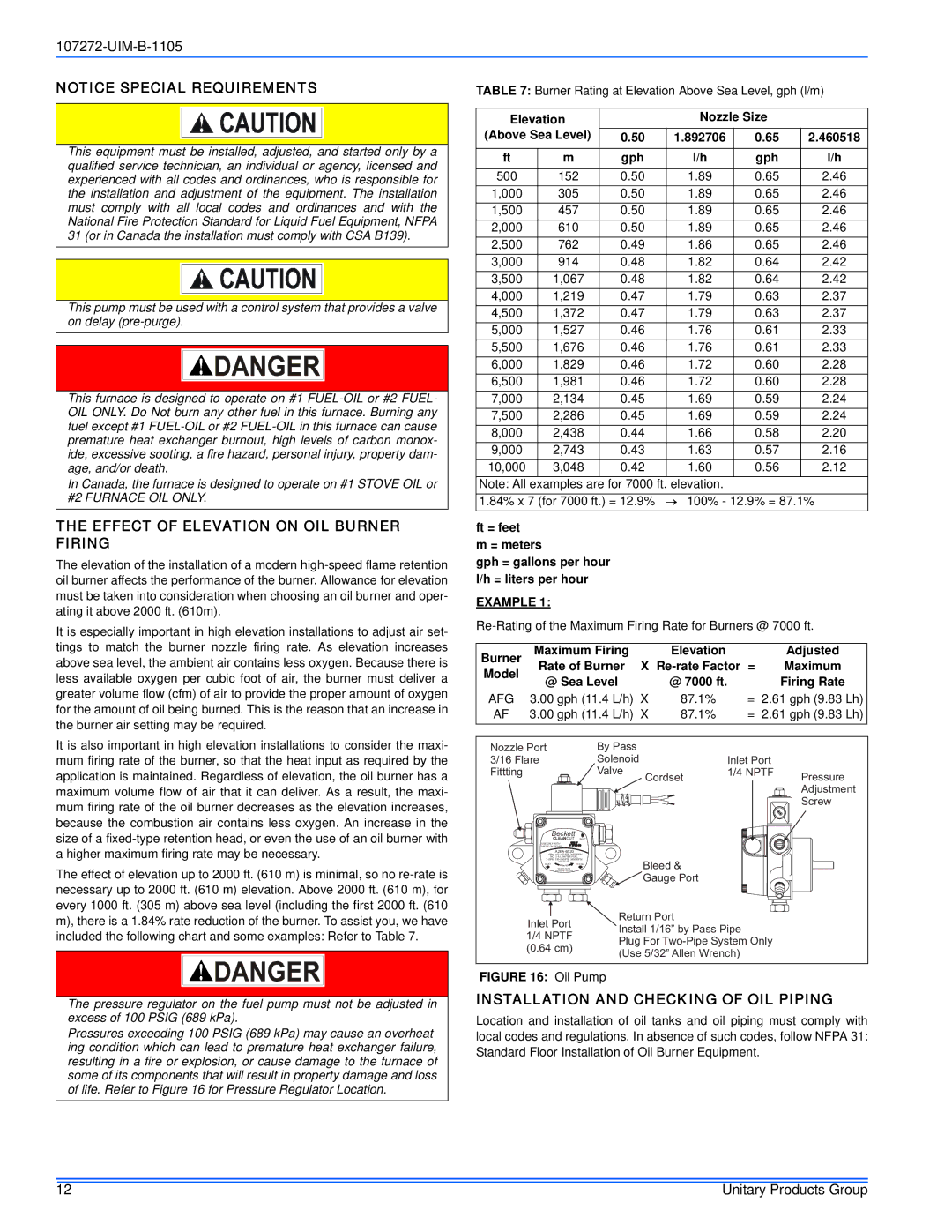
The pressure regulator on the fuel pump must not be adjusted in excess of 100 PSIG (689 kPa).
Pressures exceeding 100 PSIG (689 kPa) may cause an overheat- ing condition which can lead to premature heat exchanger failure, resulting in a fire or explosion, or cause damage to the furnace of some of its components that will result in property damage and loss of life. Refer to Figure 16 for Pressure Regulator Location.
TABLE 7: Burner Rating at Elevation Above Sea Level, gph (l/m)
Elevation |
| Nozzle Size |
| ||
(Above Sea Level) | 0.50 | 1.892706 | 0.65 | 2.460518 | |
|
|
|
|
|
|
ft | m | gph | l/h | gph | l/h |
|
|
|
|
|
|
500 | 152 | 0.50 | 1.89 | 0.65 | 2.46 |
1,000 | 305 | 0.50 | 1.89 | 0.65 | 2.46 |
1,500 | 457 | 0.50 | 1.89 | 0.65 | 2.46 |
2,000 | 610 | 0.50 | 1.89 | 0.65 | 2.46 |
2,500 | 762 | 0.49 | 1.86 | 0.65 | 2.46 |
3,000 | 914 | 0.48 | 1.82 | 0.64 | 2.42 |
3,500 | 1,067 | 0.48 | 1.82 | 0.64 | 2.42 |
4,000 | 1,219 | 0.47 | 1.79 | 0.63 | 2.37 |
4,500 | 1,372 | 0.47 | 1.79 | 0.63 | 2.37 |
5,000 | 1,527 | 0.46 | 1.76 | 0.61 | 2.33 |
5,500 | 1,676 | 0.46 | 1.76 | 0.61 | 2.33 |
6,000 | 1,829 | 0.46 | 1.72 | 0.60 | 2.28 |
6,500 | 1,981 | 0.46 | 1.72 | 0.60 | 2.28 |
7,000 | 2,134 | 0.45 | 1.69 | 0.59 | 2.24 |
7,500 | 2,286 | 0.45 | 1.69 | 0.59 | 2.24 |
8,000 | 2,438 | 0.44 | 1.66 | 0.58 | 2.20 |
9,000 | 2,743 | 0.43 | 1.63 | 0.57 | 2.16 |
10,000 | 3,048 | 0.42 | 1.60 | 0.56 | 2.12 |
Note: All | examples are for 7000 ft. elevation. |
|
| ||
1.84% x 7 (for 7000 ft.) = 12.9% | → 100% - 12.9% = 87.1% | ||||
ft = feet
m = meters
gph = gallons per hour l/h = liters per hour
EXAMPLE 1:
Burner | Maximum Firing |
| Elevation | = | Adjusted |
|
Model | Rate of Burner | X | Maximum |
| ||
@ Sea Level |
| @ 7000 ft. |
| Firing Rate | ||
|
|
| ||||
AFG | 3.00 gph (11.4 L/h) | X | 87.1% | = 2.61 gph (9.83 | Lh) | |
AF | 3.00 gph (11.4 L/h) | X | 87.1% | = | 2.61 gph (9.83 | Lh) |
. |
|
|
|
|
|
Nozzle Port |
| By Pass |
|
|
|
3/16 Flare |
| Solenoid |
| Inlet Port |
|
Fittting |
| Valve | Cordset | 1/4 NPTF | Pressure |
|
|
|
| ||
|
|
|
|
| Adjustment |
|
|
|
|
| Screw |
Beckett |
|
|
|
|
|
CLEANCUT | INLET |
|
|
|
|
USE ONLY WITH |
|
|
|
|
|
VALVE ON DELAY |
|
|
|
|
|
|
|
|
|
| |
4 GPH |
|
|
|
| |
NO. 2 & LIGHTER FUEL |
|
|
|
| |
3 GPH |
|
|
|
| |
NO. 2 FUEL |
|
| Bleed & |
|
|
INLET |
|
|
| ||
Made by Suntec |
|
|
|
| |
Exclusively for Beckett |
|
|
|
| |
|
|
| Gauge Port |
|
|
Inlet Port |
| Return Port |
|
| |
| Install 1/16” by Pass Pipe |
| |||
1/4 NPTF |
|
| |||
| Plug For |
| |||
(0.64 cm) |
|
| |||
| (Use 5/32” Allen Wrench) |
| |||
|
|
| |||
FIGURE 16: Oil Pump
INSTALLATION AND CHECKING OF OIL PIPING
Location and installation of oil tanks and oil piping must comply with local codes and regulations. In absence of such codes, follow NFPA 31: Standard Floor Installation of Oil Burner Equipment.
12 | Unitary Products Group |