|
|
|
|
|
|
|
|
|
| ||||
APPLYING FILTER PRESSURE DROP TO |
| Multiply percentage by airflow difference to obtain airflow reduction. | |||||||||||
DETERMINE SYSTEM AIRFLOW |
|
| (0.5) X |
|
|
|
|
|
| ||||
Example: For a 84,000 BTUH (38.06 kW) furnace with 1 return open- | Subtract airflow reduction value to airflow @ 0.10 w.c. (125 Pa) to | ||||||||||||
ings and operating on | obtain actual airflow @ 0.30 wc (144 Pa) ESP. |
|
|
| |||||||||
static is 0.30” w.c. (0.075 kPa). To determine the system airflow, com- | 1050 - 32.5 = 1017.5 |
|
|
|
|
|
| ||||||
plete the following steps: |
|
|
|
|
|
|
|
|
| ||||
|
|
| FINAL PROCEDURE |
|
|
|
|
| |||||
Obtain the airflow values at 0.10 w.c. (125 Pa) & 0.20 w.c. (150 Pa) |
|
|
|
|
| ||||||||
ESP. |
|
|
| Install Furnace Doors |
|
|
|
|
| ||||
Airflow @ 0.10”: 1175 CFM (60.17 m3/min) |
|
| Install the lower door first by sliding the bottom of the door down until | ||||||||||
Airflow @ 0.20”: 1110 CFM (57.62 m3/min) |
|
| the tabs on the casing base engage the slots in the bottom door end | ||||||||||
Subtract the airflow @ 0.10 w.c. (125 Pa) from the airflow @ 0.20 w.c. | cap. Then push the top of the lower door in until the door clips snap into | ||||||||||||
place. Install the upper door in a similar manner, first engaging the slots | |||||||||||||
(150 Pa) to obtain airflow difference. |
|
| |||||||||||
1175 - 1110 = |
|
| in the top of the upper door on the tabs on the casing top. Then snap | ||||||||||
|
| the bottom of the upper door into place against the casing. |
| ||||||||||
Subtract the total system static from 0.10 w.c. (125 Pa) and divide this |
| ||||||||||||
Finish and Trim |
|
|
|
|
|
| |||||||
difference by the difference in ESP values in the table, 0.20 | w.c. |
|
|
|
|
|
| ||||||
(150 Pa) - 0.10 w.c. (125 Pa), to obtain a percentage. |
|
| Alcove and Closet Installations may now be finished and trimmed as | ||||||||||
(0.30 - 0.10) / (0.20 - 0.10) = 0.5 |
|
| necessary. |
|
|
|
|
|
|
| |||
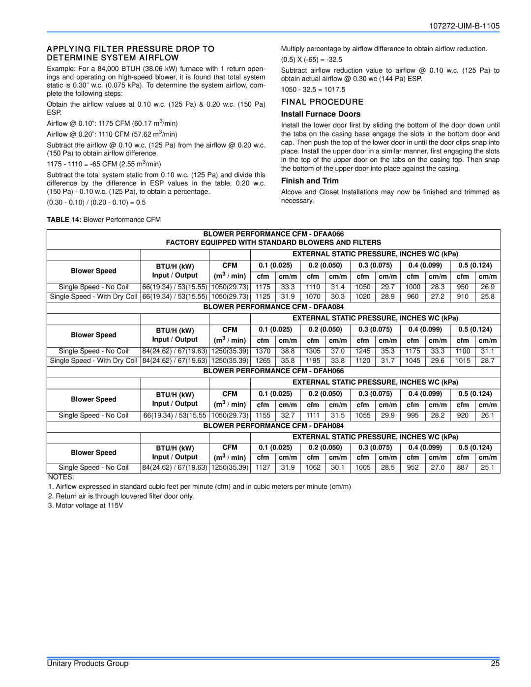
TABLE 14: Blower Performance CFM |
|
|
|
|
|
|
|
|
|
|
| ||
|
|
|
|
|
|
|
|
|
|
|
|
| |
| BLOWER PERFORMANCE CFM - DFAA066 |
|
|
|
|
|
| ||||||
| FACTORY EQUIPPED WITH STANDARD BLOWERS AND FILTERS |
|
|
|
| ||||||||
|
|
|
|
|
|
|
|
|
|
|
|
| |
|
|
|
| EXTERNAL STATIC PRESSURE, INCHES WC (kPa) |
| ||||||||
|
|
|
|
|
|
|
|
|
|
|
| ||
Blower Speed | BTU/H (kW) | CFM | 0.1 (0.025) | 0.2 (0.050) | 0.3 (0.075) | 0.4 (0.099) | 0.5 (0.124) | ||||||
Input / Output | (m3 / min) |
|
|
|
|
|
|
|
|
|
| ||
cfm | cm/m | cfm | cm/m | cfm | cm/m | cfm | cm/m | cfm | cm/m | ||||
| |||||||||||||
Single Speed - No Coil | 66(19.34) / 53(15.55) | 1050(29.73) | 1175 | 33.3 | 1110 | 31.4 | 1050 | 29.7 | 1000 | 28.3 | 950 | 26.9 | |
Single Speed - With Dry Coil | 66(19.34) / 53(15.55) | 1050(29.73) | 1125 | 31.9 | 1070 | 30.3 | 1020 | 28.9 | 960 | 27.2 | 910 | 25.8 | |
|
| BLOWER PERFORMANCE CFM - DFAA084 |
|
|
|
|
|
| |||||
|
|
|
|
|
|
|
|
|
|
|
|
| |
|
|
|
| EXTERNAL STATIC PRESSURE, INCHES WC (kPa) |
| ||||||||
|
|
|
|
|
|
|
|
|
|
|
| ||
Blower Speed | BTU/H (kW) | CFM | 0.1 (0.025) | 0.2 (0.050) | 0.3 (0.075) | 0.4 (0.099) | 0.5 (0.124) | ||||||
Input / Output | (m3 / min) | cfm | cm/m | cfm | cm/m | cfm | cm/m | cfm | cm/m | cfm | cm/m | ||
| |||||||||||||
Single Speed - No Coil | 84(24.62) / 67(19.63) | 1250(35.39) | 1370 | 38.8 | 1305 | 37.0 | 1245 | 35.3 | 1175 | 33.3 | 1100 | 31.1 | |
Single Speed - With Dry Coil | 84(24.62) / 67(19.63) | 1250(35.39) | 1265 | 35.8 | 1195 | 33.8 | 1120 | 31.7 | 1045 | 29.6 | 1015 | 28.7 | |
|
| BLOWER PERFORMANCE CFM - DFAH066 |
|
|
|
|
|
| |||||
|
|
|
|
|
|
|
|
|
|
|
|
| |
|
|
|
| EXTERNAL STATIC PRESSURE, INCHES WC (kPa) |
| ||||||||
|
|
|
|
|
|
|
|
|
|
|
| ||
Blower Speed | BTU/H (kW) | CFM | 0.1 (0.025) | 0.2 (0.050) | 0.3 (0.075) | 0.4 (0.099) | 0.5 (0.124) | ||||||
Input / Output | (m3 / min) |
|
|
|
|
|
|
|
|
|
| ||
cfm | cm/m | cfm | cm/m | cfm | cm/m | cfm | cm/m | cfm | cm/m | ||||
| |||||||||||||
Single Speed - No Coil | 66(19.34) / 53(15.55 | 1050(29.73) | 1155 | 32.7 | 1111 | 31.5 | 1055 | 29.9 | 995 | 28.2 | 920 | 26.1 | |
|
| BLOWER PERFORMANCE CFM - DFAH084 |
|
|
|
|
|
| |||||
|
|
|
|
|
|
|
|
|
|
|
|
| |
|
|
|
| EXTERNAL STATIC PRESSURE, INCHES WC (kPa) |
| ||||||||
|
|
|
|
|
|
|
| ||||||
Blower Speed | BTU/H (kW) | CFM | 0.1 (0.025) | 0.2 (0.050) | 0.3 (0.075) | 0.4 (0.099) | 0.5 (0.124) | ||||||
Input / Output | (m3 / min) | cfm | cm/m | cfm | cm/m | cfm | cm/m | cfm | cm/m | cfm | cm/m | ||
| |||||||||||||
Single Speed - No Coil | 84(24.62) / 67(19.63) | 1250(35.39) | 1127 | 31.9 | 1062 | 30.1 | 1005 | 28.5 | 952 | 27.0 | 887 | 25.1 | |
NOTES: |
|
|
|
|
|
|
|
|
|
|
|
| |
1.Airflow expressed in standard cubic feet per minute (cfm) and in cubic meters per minute (cm/m)
2.Return air is through louvered filter door only.
3.Motor voltage at 115V
Unitary Products Group | 25 |