EXTERIOR ROOF JACK EXTENSION
Application
Available to comply with instances in which the roof jack crown needs to be raised to meet a roof clearance requirement. One extension will raise the roof jack crown by 18” 45.7 cm).
ROOF JACK
Failure to follow all venting instructions can result in fire, asphyxiation, or explosion.
Only use the appropriate roof jack. See Figures 26, 27, 30, and 31 for correct application.
Do not exceed the maximum height as determined from Table 9. Installer should allow an additional
EXISTING FURNACE REPLACEMENT
If this furnace replaces an existing furnace, do the following:
1.If a 2nd roof, roof cap or addition has been made to the existing roof of the home, remove the old roof jack completely! To avoid the possibility of an improperly installed pipe or gaps in the old roof jack, INSTALL A NEW ROOF JACK. Your ceiling and roof height will determine the correct roof jack to use.
2.After unpacking the roof jack, check the rain caps. Insure they are not damaged, tilted or crooked. Do not twist, crush or sit on the roof caps during installation. Damaged roof caps will cause improper furnace operation. The furnace will not heat properly and could result in explosion.
3.Before inserting the roof jack into the furnace top, inspect the fur- nace flue and combustion air opening for debris or insulation which might have fallen in during
4.After installing roof jack on furnace top collar, check to make sure there is no gap in back or side between the pipe collar and the fur- nace casing top.
5.Use only the pipes provided with the roof jack assembly. Do not add to or adapt other sheet metal pipes. Do not cut, insert or add other pipes to this assembly.
6.In no case should there be a gap between sections of the flue pipe or the combustion air pipe. If necessary to prevent excessive air leakage, the installer should seal joints in the combustion air tube with Chemcaulk 900 sealant or other suitable sealant.
NEW HOME INSTALLATION
If this furnace is installed in a new home do the following:
1.Inspect the furnace top collars for signs of insulation or ceiling debris which might have fallen in during cutting of the ceiling and roof holes. Remove all debris before continuing.
The vent and combustion air openings in the top of the furnace must be free of construction debris before the Roof Jack is installed. Failure to ensure that these openings are free will result in excessive amounts of CARBON MONOXIDE and elevated heat exchanger temperatures which can lead to premature heat exchanger failure, resulting in a fire or explosion or cause damage to the furnace or some of its components that will result in property damage and loss of life.
2.After unpacking the roof jack, check the rain caps. Insure they are not damaged, tilted or crooked. Do not twist, crush or sit on the roof caps during installation. Damaged roof caps will cause improper furnace operation. The furnace will not heat properly and could result in explosion.
3.Before inserting the vent pipe into the furnace top, inspect the fur- nace flue and combustion air opening for debris or insulation which have fallen in during
4.After installing roof jack on furnace top collar, check to make sure there is no gap in back or side between the pipe collar and the fur- nace casing top. If necessary to prevent excessive air leakage, the installer should seal joints in the combustion air tube with Chem- caulk 900 sealant or other suitable sealant.
INSTALLATION IN SNOW REGIONS
When the combustion air pipe inlet is covered or blocked with snow, the furnace will not operate properly due to the depleted combustion air supply.
Therefore, if the furnace will be located in regions where snow accumu- lation on the roof exceeds 4" or in H.U.D. Snow Load Zones, a roof jack extension and PVC combustion air inlet extension is recommended. Refer to Figure 26 or 27.
COMBUSTION AIR INLET
All combustion air pipe and fittings must conform to American National Standards Institute (ANSI) standards and American Society for Testing and Materials (ASTM) standards D1785 (Schedule 40 PVC), D2665
1.Mark vertical combustion air inlet centerline on ceiling. Cut hole for combustion air inlet piping. Clearance to combustible materials is not required.
2.Cut hole in roof. Provide minimum 12” (30.5 cm) vertical separa- tion between combustion air inlet pipe and roof jack vent cap. Clearance to combustible materials is not required.
3.Route piping through ceiling and holes. Provide firestop as required.
4.Insert combustion air inlet coupling into casing. See Figure 26 or 27.
5.Slide PVC pipe into coupling. Use a hose clamp to secure the PVC pipe to the coupling.
6.Complete piping through roof. Provide flashing at roof penetration.
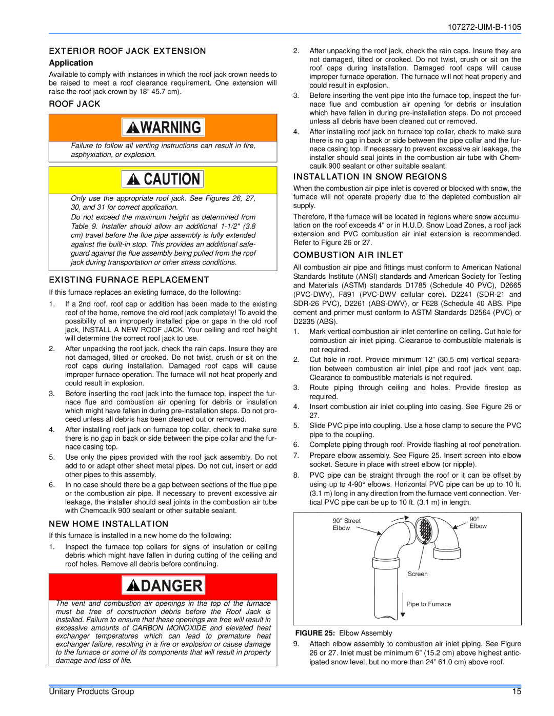
7.Prepare elbow assembly. See Figure 25. Insert screen into elbow socket. Secure in place with street elbow (or nipple).
8.PVC pipe can be straight through the roof or it can be offset by using up to
90° Street | 90° | |
Elbow | ||
Elbow | ||
|
Screen
Pipe to Furnace
FIGURE 25: Elbow Assembly
9.Attach elbow assembly to combustion air inlet piping. See Figure 26 or 27. Inlet must be minimum 6” (15.2 cm) above highest antic- ipated snow level, but no more than 24” 61.0 cm) above roof.
Unitary Products Group | 15 |