SPECIFICATIONS
Models:
Table 11 lists the major features and the applicable wiring diagram num- bers for the R7184.
Timing:
1.Safe Start Check: 5 seconds (approximately)
2.
3.Burner
NOTE:
4.Lockout: 15, 30, or 45 seconds
5.Recycle: 60 seconds (fixed).
6.Ignition Carryover: 10 seconds (fixed).
Electrical Ratings:
Inputs:
a.Voltage: 102 to 132 VAC, 120 VAC nominal.
b.Current: 100 mA plus burner motor, valve and igniter loads.
c.Frequency: 60 Hz.
Outputs:
a.Burner: 120 VAC, 10 full load amperes (FLA), 60 locked rotor amperes (LRA).
b.Valve: 120 VAC, 1A
c.Igniter: 120 VAC, 360 VA
d.Alarm: 30 VAC, 2A
e.Thermostat Current Available: 100mA
F.EnviraCOMTM Current Available: 150mA
NOTE: Reduce burner FLA rating by igniter load. For example, if the igniter draws 3A (120 VAC, 360 VA), reduce the burner motor FLA to 7A.
SECTION VIII: START-UP AND
ADJUSTMENTS
The initial
IMPORTANT: All electrical connections made in the field and in the fac- tory should be checked for proper tightness.
When the oil line is initially connected to the furnace, the tubing may be full of air. In order to purge this air, it is recommended that the bleed valve be loosened until no air bubbles are detected in the plastic tubing. If burner does not light, press the reset button on the primary control once only and bleed oil pump again. If burner still does not light, turn off the power to the furnace and call a qualified service technician. DO
NOT CONTINUE TO PRESS THE RESET BUTTON ON THE PRI- MARY CONTROL.
TOOLS AND INFORMATION THAT WILL BE REQUIRED IN ORDER TO PROPERLY PERFORM THE FURNACE STARTUP PROCEDURE.
1.You will need a thermometer or portable digital thermometer to read the supply and return air temperatures.
2.You will need a pressure gauge that has the ability to read pres- sures between 0 - 100 PSIG (0 - 689 kPa) in order to measure the oil pump pressures.
3.You will need a 3/32” Allen wrench for the pressure port adjust- ment screw in the oil pump.
4.You will need 1 piece of 1/4” (0.63 cm) ID flexible tubing that is 12” (30 cm) in length
5.You will need a clear plastic jug.
6.You will need a 7/16” open end or box wrench.
7.You will need a 1/4” brass NPT x flare fitting.
These items are required in order to properly perform the required start- up procedure.
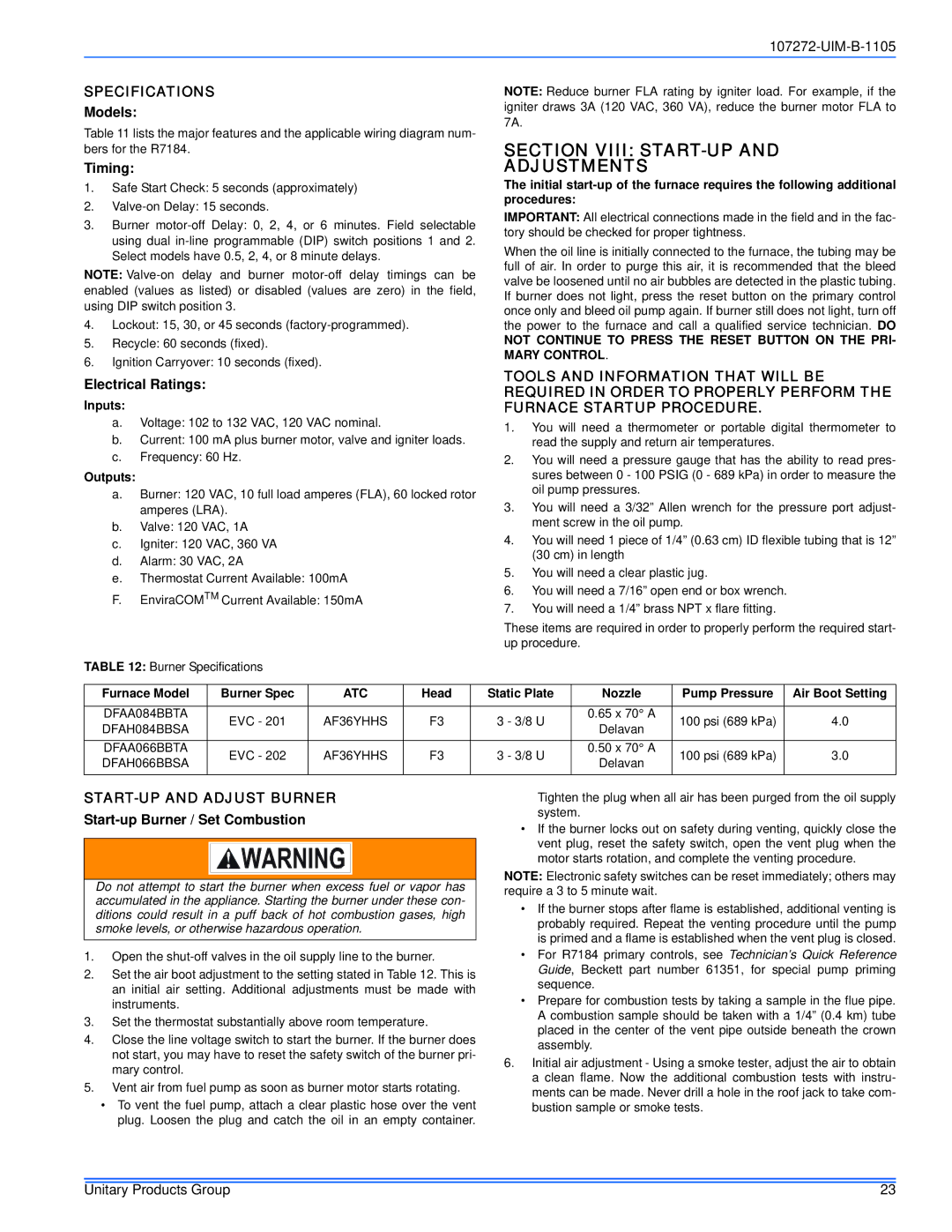
TABLE 12: Burner Specifications
Furnace Model | Burner Spec | ATC | Head | Static Plate | Nozzle | Pump Pressure | Air Boot Setting | |
|
|
|
|
|
|
|
| |
DFAA084BBTA | EVC - 201 | AF36YHHS | F3 | 3 - 3/8 U | 0.65 x 70° A | 100 psi (689 kPa) | 4.0 | |
DFAH084BBSA | Delavan | |||||||
|
|
|
|
|
| |||
|
|
|
|
|
|
|
| |
DFAA066BBTA | EVC - 202 | AF36YHHS | F3 | 3 - 3/8 U | 0.50 x 70° A | 100 psi (689 kPa) | 3.0 | |
DFAH066BBSA | Delavan | |||||||
|
|
|
|
|
| |||
|
|
|
|
|
|
|
|
START-UP AND ADJUST BURNER
Start-up Burner / Set Combustion
Do not attempt to start the burner when excess fuel or vapor has accumulated in the appliance. Starting the burner under these con- ditions could result in a puff back of hot combustion gases, high smoke levels, or otherwise hazardous operation.
1.Open the
2.Set the air boot adjustment to the setting stated in Table 12. This is an initial air setting. Additional adjustments must be made with instruments.
3.Set the thermostat substantially above room temperature.
4.Close the line voltage switch to start the burner. If the burner does not start, you may have to reset the safety switch of the burner pri- mary control.
5.Vent air from fuel pump as soon as burner motor starts rotating.
•To vent the fuel pump, attach a clear plastic hose over the vent plug. Loosen the plug and catch the oil in an empty container.
Tighten the plug when all air has been purged from the oil supply system.
•If the burner locks out on safety during venting, quickly close the vent plug, reset the safety switch, open the vent plug when the motor starts rotation, and complete the venting procedure.
NOTE: Electronic safety switches can be reset immediately; others may require a 3 to 5 minute wait.
•If the burner stops after flame is established, additional venting is probably required. Repeat the venting procedure until the pump is primed and a flame is established when the vent plug is closed.
•For R7184 primary controls, see Technician’s Quick Reference Guide, Beckett part number 61351, for special pump priming sequence.
•Prepare for combustion tests by taking a sample in the flue pipe. A combustion sample should be taken with a 1/4” (0.4 km) tube placed in the center of the vent pipe outside beneath the crown assembly.
6.Initial air adjustment - Using a smoke tester, adjust the air to obtain a clean flame. Now the additional combustion tests with instru- ments can be made. Never drill a hole in the roof jack to take com- bustion sample or smoke tests.
Unitary Products Group | 23 |