INITIAL START UP
1.Read the applicable sequence of gas control operation in the Operation and Troubleshooting section before proceeding.
2.Move the gas valve control switch to the “OFF” position.
3.Adjust the primary air. Set the damper to the start up settings.
4.On new gas line installations, air may be trapped in the line, the burner may experience several lockouts until all the air is purged from the lines.
5.Turn on the main electrical power and set the thermostat to call for heat. Allow the burner to run a MINIMUM of 5 minutes to purge combustion chamber and appliance heat exchanger.
6.Set the thermostat below room temperature, shutting the burner “OFF”.
7.Move the gas valve control switch to the “ON” position.
8.Set the thermostat or operating control to call for heat. The burner will start and go through the applicable sequence of burner/pri- mary gas control operation, refer to step 1.
9.Once burner is running, adjust the orifice manifold pressure regu- lator as described in Pressure Regulator Adjustment.
Be sure to relight any gas appliances that were turned off at the start of this input check.
CHECKING THE GAS PRESSURES
1.The pressure ports on the gas valve are marked OUT and INLET.
2.The manifold pressure must be taken at the port marked OUT.
3.The inlet gas supply pressure must be taken at the port marked IN LET.
4.Using a 3/32” (0.2 cm) Allen wrench, loosen the set screw by turn- ing it 1 turn counter clockwise. DO NOT REMOVE THE SET SCREW FROM THE PRESSURE PORT.
5.Use the 4” (10.2 cm) piece of 3/8” (0.9 cm) tubing to connect the positive side of the manometer to the gas valve pressure refer- ence port. Refer to Figure 43 for connection details.
TABLE 20: Inlet Gas Pressure Range
INLET GAS PRESSURE RANGE
| Natural Gas | Propane (LP) |
Minimum | 4.5” W.C. (1.12 kPa) | 8.0” W.C. (1.99 kPa) |
|
|
|
Maximum | 10.5” W.C. (2.61 kPa) | 13.0” (3.24 kPa) W.C. |
|
|
|
IMPORTANT: The inlet gas pressure operating range table specifies the minimum and maximum gas line pressures required for safe fur- nace operation.
The minimum inlet gas pressure required to obtain the BTU input speci- fied on the rating plate and in these instructions is shown below:
•7.0” w.c. (1.74 kPa) for Natural Gas
•11.0” w.c. (2.74 kPa) for Propane (LP) Gas
ADJUSTMENT OF MANIFOLD GAS PRESSURE
Manifold gas pressure may be measured at the gas valve.
Turn gas off at the ball valve or gas cock on gas supply line before the gas valve. Find the pressure ports on the gas valve marked OUT and INLET.
IMPORTANT: The cap for the pressure regulator must be removed entirely to gain access to the adjustment screw. Loosening or tightening the cap does not adjust the flow of gas.
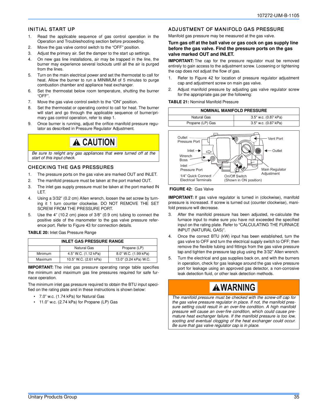
1.Refer to Figure 42 for location of pressure regulator adjustment cap and adjustment screw on main gas valve.
2.Adjust manifold pressure by adjusting gas valve regulator screw for the appropriate gas per the following:
TABLE 21: Nominal Manifold Pressure
NOMINAL MANIFOLD PRESSURE
Natural Gas | 3.5" w.c. (0.87 kPa) |
Propane (LP) Gas | 3.5" w.c. (0.87 kPa) |
Outlet |
| Vent Port |
Pressure Port |
| |
|
| |
Inlet |
| Outlet |
Wrench | OFF |
|
Boss |
| |
Inlet | ON |
|
Pressure Port | Main Regulator | |
1/4” Quick Connect | On/Off Switch | Adjustment |
| ||
Electrical Terminals | (Shown in ON position) | |
FIGURE 42: Gas Valve
IMPORTANT: If gas valve regulator is turned in (clockwise), manifold pressure is increased. If screw is turned out (counter clockwise), mani- fold pressure will decrease.
3.After the manifold pressure has been adjusted,
4.Once the correct BTU (kW) input has been established, turn the gas valve to OFF and turn the electrical supply switch to OFF; then remove the flexible tubing and fittings from the gas valve pressure tap and tighten the pressure tap plug using the 3/32” Allen wrench.
5.Turn the electrical and gas supplies back on, and with the burners in operation, check for gas leakage around the gas valve pressure port for leakage using an approved gas detector, a
The manifold pressure must be checked with the
Unitary Products Group | 35 |