SECTION X: GAS GUN BURNER
These instructions were prepared for the guidance of those installing this particular gas conversion burner. While they apply in principle to all installations, they should not be interpreted as meaning the only safe and economical way to install a conversion burner. It may be necessary to deviate from these instructions in some instances in order to comply with local gas company rules or codes in effect in the area in which the installation is made. It is recommended that the installer confer with the local gas company and with the proper municipal officials regarding any specific code or regulation governing the installation of gas conversion burners, the installation must conform with local codes or, in the absence of local codes, with the American National Standard Installa- tion of Domestic Gas Conversion Burners, Z21.8 latest edition, and the National Fuel Gas Code, ANSI
Safe and economical operation of the burner throughout its service life is dependent to a large extent upon its proper installation in the heating appliance. Therefore, we may impress upon the installer that good clean workmanlike installations mean satisfied customers.
PREPARATION OF COMBUSTION CHAMBER
The power gas burner is designed for “inshot” firing into a refactory lined combustion chamber constructed in the furnace originally designed for oil firing.
When converting oil designed furnaces, it is recommended that the same combustion chamber be used with the oil burner. If the blast tube opening into the combustion chamber is larger than the 4" (101.6 mm) diameter, high temperature cement should be used to reduce the open- ing to 4" (101.6 mm) diameter.
.
An overpressure protection device, such as a pressure regulator, must be installed in the gas piping system upstream of the furnace and must act to limit the downstream pressure to the gas valve so it does not exceed 0.5 PSI (14" w.c. (3.48 kPa). Pressures exceeding
0.5PSI (14” w.c. (3.48 kPa) at the gas valve will cause damage to the gas valve, resulting in a fire or explosion or cause damage to the furnace or some of its components that will result in property damage and loss of life.
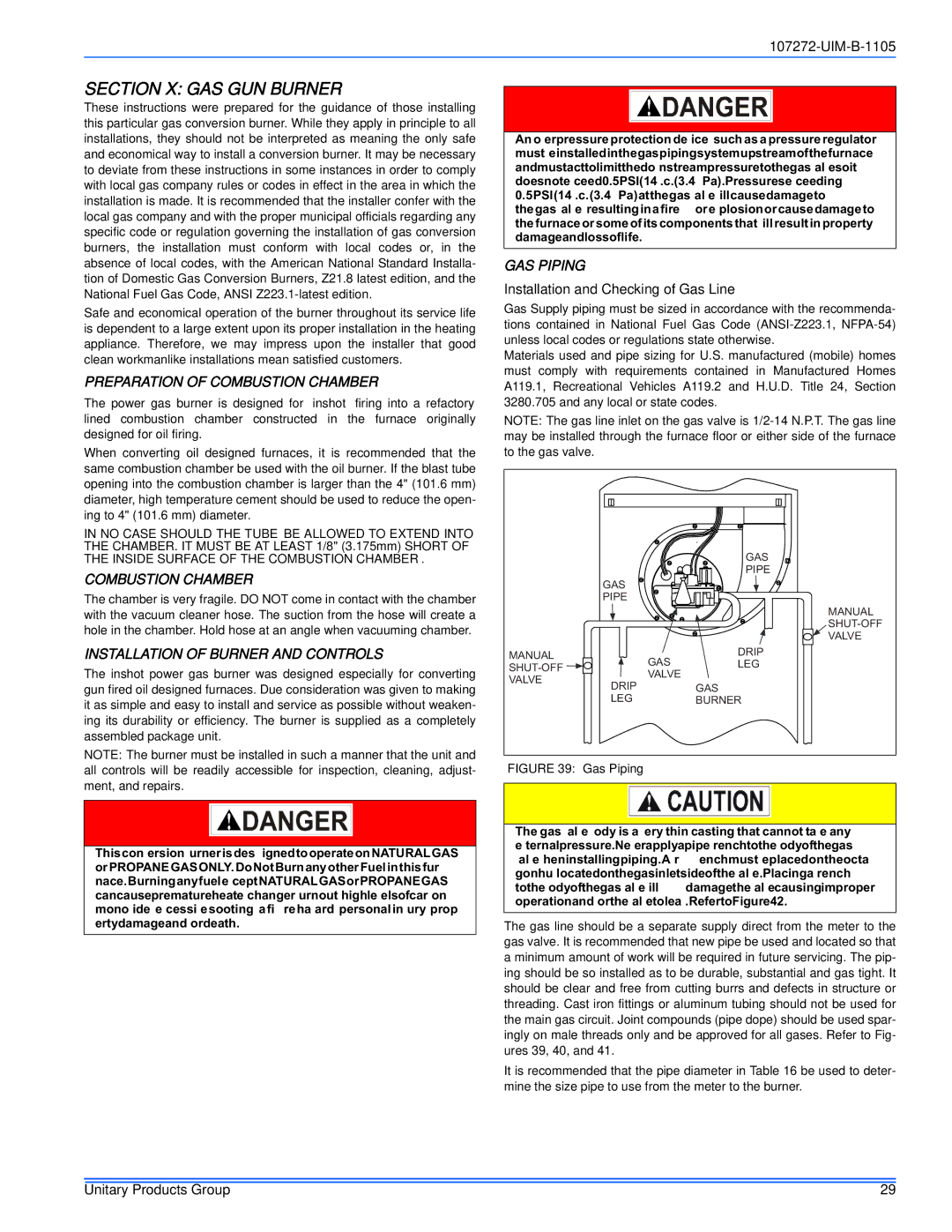
GAS PIPING
Installation and Checking of Gas Line
Gas Supply piping must be sized in accordance with the recommenda- tions contained in National Fuel Gas Code
Materials used and pipe sizing for U.S. manufactured (mobile) homes must comply with requirements contained in Manufactured Homes A119.1, Recreational Vehicles A119.2 and H.U.D. Title 24, Section 3280.705 and any local or state codes.
NOTE: The gas line inlet on the gas valve is
IN NO CASE SHOULD THE TUBE BE ALLOWED TO EXTEND INTO THE CHAMBER. IT MUST BE AT LEAST 1/8" (3.175mm) SHORT OF THE INSIDE SURFACE OF THE COMBUSTION CHAMBER.
COMBUSTION CHAMBER
The chamber is very fragile. DO NOT come in contact with the chamber with the vacuum cleaner hose. The suction from the hose will create a hole in the chamber. Hold hose at an angle when vacuuming chamber.
INSTALLATION OF BURNER AND CONTROLS
The inshot power gas burner was designed especially for converting gun fired oil designed furnaces. Due consideration was given to making it as simple and easy to install and service as possible without weaken- ing its durability or efficiency. The burner is supplied as a completely assembled package unit.
NOTE: The burner must be installed in such a manner that the unit and
MANUAL ![]() VALVE
VALVE
| GAS |
| PIPE |
GAS |
|
PIPE |
|
| DRIP |
GAS | LEG |
VALVE |
|
DRIP | GAS |
LEG | BURNER |
MANUAL
all controls will be readily accessible for inspection, cleaning, adjust- ment, and repairs.
This conversion burner is designed to operate on NATURAL GAS or PROPANE GAS ONLY. Do Not Burn any other Fuel in this fur- nace. Burning any fuel except NATURAL GAS or PROPANE GAS can cause premature heat exchanger burnout, high levels of carbon monoxide, excessive sooting, a fire hazard, personal injury, prop- erty damage and /or death.
FIGURE 39: Gas Piping
The gas valve body is a very thin casting that cannot take any external pressure. Never apply a pipe wrench to the body of the gas valve when installing piping. A wrench must be placed on the octa- gon hub located on the gas inlet side of the valve. Placing a wrench to the body of the gas valve will damage the valve causing improper operation and/or the valve to leak. Refer to Figure 42.
The gas line should be a separate supply direct from the meter to the gas valve. It is recommended that new pipe be used and located so that a minimum amount of work will be required in future servicing. The pip- ing should be so installed as to be durable, substantial and gas tight. It should be clear and free from cutting burrs and defects in structure or threading. Cast iron fittings or aluminum tubing should not be used for the main gas circuit. Joint compounds (pipe dope) should be used spar- ingly on male threads only and be approved for all gases. Refer to Fig- ures 39, 40, and 41.
It is recommended that the pipe diameter in Table 16 be used to deter- mine the size pipe to use from the meter to the burner.
Unitary Products Group | 29 |