|
|
|
|
|
|
|
|
|
|
|
|
|
|
|
|
|
|
| |||
DFAH Furnaces: |
|
|
|
|
|
|
|
|
|
|
|
|
|
|
|
|
|
|
| ||
|
|
|
|
|
|
|
|
|
|
|
|
|
|
|
|
|
|
| |||
If a matching cooling coil is used, it may be placed directly on the fur- |
|
|
|
|
|
|
|
|
|
|
|
|
|
|
|
|
|
|
| ||
nace outlet and sealed to prevent leakage. Follow the coil instructions |
|
|
|
|
|
|
|
|
|
|
|
|
|
|
|
|
|
|
| ||
for installing the supply plenum. On all installations without a coil, a |
|
|
|
|
|
|
|
|
|
|
|
|
|
|
|
|
|
|
| ||
|
|
|
|
|
|
|
|
|
|
|
|
|
|
|
|
|
|
| |||
removable access panel is recommended in the outlet duct such that |
|
|
|
|
|
|
|
|
|
|
|
|
|
|
|
|
|
|
| ||
smoke or reflected light would be observable inside the casing to indi- |
|
|
|
|
|
|
|
|
|
|
|
|
|
|
|
|
|
|
| ||
|
|
|
|
|
|
|
|
|
|
|
|
|
|
|
|
|
|
| |||
|
|
|
|
|
|
|
|
|
|
|
|
|
|
|
|
|
|
| |||
cate the presence of leaks in the heat exchanger. This access cover | Blend Air |
|
|
|
|
|
|
|
|
|
|
|
|
|
|
|
| ||||
shall be attached in such a manner as to prevent leaks. | Flex Duct |
|
|
|
|
|
|
|
|
|
|
|
|
|
|
|
| ||||
RETURN AIR REQUIREMENTS | Blend Air |
|
|
|
|
|
|
|
|
|
|
|
|
|
|
|
| ||||
|
|
|
|
|
|
|
|
|
|
|
|
|
|
|
|
|
| ||||
Closet Installations | Damper |
|
|
|
|
|
|
|
|
|
|
|
|
|
|
|
| ||||
|
|
|
|
|
|
|
|
|
|
|
|
|
|
|
| ||||||
|
|
|
|
|
|
|
|
|
|
|
|
|
|
|
| ||||||
|
|
|
|
|
|
|
|
|
|
|
|
|
|
|
| ||||||
|
|
|
|
|
|
|
|
|
|
|
|
|
|
|
| ||||||
|
|
|
|
|
|
|
|
|
|
|
|
|
|
|
|
|
|
| |||
|
|
|
|
|
|
|
|
|
|
|
|
|
|
|
|
|
|
| |||
|
|
|
|
|
|
|
|
|
|
|
|
|
|
|
|
|
|
| |||
|
|
|
|
|
|
|
|
|
|
|
|
|
|
|
|
|
|
| |||
|
|
|
|
|
|
|
|
|
|
|
|
|
|
|
|
|
|
| |||
|
|
|
|
|
|
|
|
|
|
|
|
|
|
|
|
|
|
| |||
|
|
|
|
|
|
|
|
|
|
|
|
|
|
|
|
|
|
| |||
|
|
|
|
|
|
|
|
|
|
|
|
|
|
|
|
|
|
| |||
|
|
|
|
|
|
|
|
|
|
|
|
|
|
|
|
|
|
| |||
|
|
|
|
|
|
|
|
|
|
|
|
|
|
|
|
|
|
| |||
|
|
|
|
|
|
|
|
|
|
|
|
|
|
|
|
|
|
| |||
Additional Requirements |
|
|
|
|
|
|
|
|
|
|
|
|
|
|
|
|
|
|
| ||
|
|
|
|
|
|
|
|
|
|
|
|
|
|
|
|
|
|
| |||
|
|
|
|
|
|
|
|
|
|
|
|
|
|
|
|
|
|
| |||
|
|
|
|
|
|
|
|
|
|
|
|
|
|
|
|
|
|
| |||
|
|
|
|
|
|
|
|
|
|
|
|
|
|
|
|
|
|
| |||
|
|
|
|
|
|
|
|
|
|
|
|
|
|
|
|
|
|
| |||
|
|
|
|
|
|
|
|
|
|
|
|
|
|
|
|
|
|
| |||
|
|
|
|
|
|
|
|
|
|
|
|
|
|
|
|
|
|
| |||
|
|
|
|
|
|
|
|
|
|
|
|
|
|
|
|
|
|
| |||
|
|
|
|
|
|
|
|
|
|
|
|
|
|
|
|
|
|
| |||
|
|
|
|
|
|
|
|
|
|
|
|
|
|
|
|
|
|
| |||
Additional requirements for floor and ceiling return system for closet |
|
|
|
|
|
|
|
|
|
|
|
|
|
|
|
|
|
|
| ||
|
|
|
|
|
|
|
|
|
|
|
|
|
|
|
|
|
|
| |||
|
|
|
|
|
|
|
|
|
|
|
|
|
|
|
|
|
|
| |||
|
|
|
|
|
|
|
|
|
|
|
|
|
|
|
|
|
|
| |||
|
|
|
|
|
|
|
|
|
|
|
|
|
|
|
|
|
|
| |||
|
|
|
|
|
|
|
|
|
|
|
|
|
|
|
|
|
|
| |||
|
|
|
|
|
|
|
|
|
|
|
|
|
|
|
|
|
|
| |||
|
|
|
|
|
|
|
|
|
|
|
|
|
|
|
|
|
|
| |||
|
|
|
|
|
|
|
|
|
|
|
|
|
|
|
|
|
|
| |||
|
|
|
|
|
|
|
|
|
|
|
|
|
|
|
|
|
|
| |||
|
|
|
|
|
|
|
|
|
|
|
|
|
|
|
|
|
|
| |||
|
|
|
|
|
|
|
|
|
|
|
|
|
|
|
|
|
|
| |||
installed sealed combustion heating appliances are given in the next |
|
|
|
|
|
|
|
|
|
|
|
|
|
|
|
|
|
|
| ||
|
|
|
|
|
|
|
|
|
|
|
|
|
|
|
|
|
|
| |||
paragraph. |
|
|
|
|
|
|
|
|
|
|
|
|
|
|
|
|
|
|
| ||
Floor or Ceiling Return Air System |
|
|
|
|
|
|
|
|
|
|
|
|
|
|
| Floor | |||||
|
|
|
|
|
|
|
|
|
|
|
|
|
|
|
|
|
|
|
|
| |
|
|
|
|
|
|
|
|
|
|
|
|
|
|
|
|
|
|
|
|
| |
|
|
|
|
|
|
|
|
|
|
|
|
|
|
|
|
|
| ||||
Listed in the next paragraph are the conditions to be met by Manufac- | WARM AIR DUCT | DUCT CONNECTOR | |||||||||||||||||||
|
|
|
|
|
|
|
|
|
|
|
|
|
|
|
|
|
|
| |||
tured Home Manufacturers to have U.L. acceptance of |
|
|
|
|
|
|
|
|
|
|
|
|
|
|
|
|
|
|
| ||
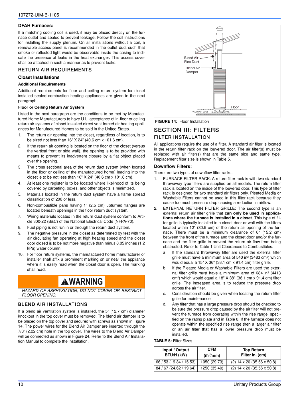
FIGURE 14: Floor Installation |
|
|
|
|
|
|
|
|
|
|
|
|
|
|
|
| |||||
return air systems of closet installed direct vent forced air heating appli- |
|
|
|
|
|
|
|
|
|
|
|
|
|
|
|
| |||||
SECTION III: FILTERS | |||||||||||||||||||||
ances for Manufactured Homes to be sold in the United States. | |||||||||||||||||||||
1. | The return air opening into the closet, regardless of location, is to | FILTER INSTALLATION |
|
|
|
|
|
|
|
|
|
|
|
|
|
|
|
| |||
| be sized not less than 16” X 24” (40.6 cm x 101.6 cm). |
|
|
|
|
|
|
|
|
|
|
|
|
|
|
|
| ||||
| All applications require the use of a filter. A standard air filter is located | ||||||||||||||||||||
2. | If the return air opening is located on the floor of the closet (versus | ||||||||||||||||||||
in the return filter rack on the louvered door. The air filter(s) must be | |||||||||||||||||||||
| the vertical front or side wall), the opening is to be provided with | ||||||||||||||||||||
| replaced with air filter(s) that | are the same size and same type. | |||||||||||||||||||
| means to prevent its inadvertent closure by a flat object placed | ||||||||||||||||||||
over the opening. | Replacement filter size is shown in Table 5. |
|
3.The cross sectional area of the return duct system (when located in the floor or ceiling of the manufactured home) leading into the closet is to be not less than 16” X 24” (40.6 cm x 101.6 cm).
4.At least one register is to be located where likelihood of its being covered by carpeting, boxes, and other objects is minimized.
5.Materials located in the return duct system have a flame spread classification of 200 or less.
6.
7.Wiring materials located in the return duct system conform to Arti- cle
8.Fuel piping is not run in or through the return duct system.
9.The negative pressure in the closet as determined by test with the air circulating fan operating at high heating speed and the closet door closed is to be not more negative than minus 0.05 inches (1.2 kPa) water column.
10.For floor return systems, the manufactured home manufacturer or installer shall affix a prominent marking on or near the appliance where it is easily read when the closet door is open. The marking shall read:
HAZARD OF ASPHYXIATION, DO NOT COVER OR RESTRICT FLOOR OPENING.
BLEND AIR INSTALLATIONS
If a blend air ventilation system is installed, the 5” (12.7 cm) diameter knockout in the top cover must be removed. The blend air damper is to be placed on the top cover and secured with screws as shown in Figure
14.The power wires for the Blend Air Damper are inserted through the 7/8” (2.22 cm) hole in the top cover. The wires to the Blend Air Damper will be connected as shown in Figure 24. Refer to the Blend Air Installa- tion Manual to complete the installation.
Downflow Filters:
There are two types of downflow filter racks.
1.FURNACE FILTER RACK: A return filter rack is with two standard throwaway type filters are supplied on all models. The return filter rack is located on the inside of the louvered door. This type of filter rack is designed for two standard air filters only. Pleated Media or Washable Filters cannot be used in this filter rack because they cause too much pressure drop causing a reduction in airflow.
2.EXTERNAL RETURN FILTER GRILLE: The second type is an external return air filter grille that can only be used in applica- tions where the furnace is installed in a closet. This type of fil- ter grille is typically installed in a closet door or wall with the filters located within 12" (30.5 cm) of the return air opening of the fur- nace. There must be a minimum clearance of 6" (15.2 cm) between the front of the furnace and the closet door and/or the fur- nace and the filter grille to prevent the return air flow from being obstructed. Refer to Table 1 Unit Clearances to Combustibles.
a.If the standard throwaway filter are used the external filter grille must have a minimum area of 540 in² (3483 cm²) which would equal a 15" X 36" (38.1 cm x 91.4 cm) filter grille.
b.If the Pleated Media or Washable Filters are used the exter- nal filter grille must have a minimum area of 684 in² (4413 cm²) which would equal a 18" X 38" (38.1 cm x 91.4 cm) filter grille. The increased area is to reduce the pressure drop across the air filter.
c.Consideration should be given when locating the return filter grille for maintenance.
d.Any filter that has a large pressure drop should be checked to be sure the pressure drop caused by the air filter will not pre- vent the furnace from operating within the rise range, speci- fied on the rating plate and in Table 8. If the furnace does not operate within the specified rise range then a larger air filter or an air filter that has a lower pressure drop must be installed.
TABLE 5: Filter Sizes
Input / Output | CFM | Top Return |
BTU/H (kW) | (m3/mm) | Filter In. (cm) |
66 / 53 (19.34 / 15.53) | 1050 (29.73) | (2) 14 x 20 (35.56 x 50.8) |
84 / 67 (24.62 / 19.64) | 1250 (35.40) | (2) 14 x 20 (35.56 x 50.8) |
10 | Unitary Products Group |