NOTE: A burner with an electronic igniter or a PSC motor will have a lower operating current. The actual load should be determined by a cur- rent meter.
NOTE: See appliance manufacturer’s burner specifications for required outlet pressure. Pressure is 100 psig (689 kPa) unless otherwise noted.
SUPPLY VOLTAGE CONNECTIONS
1.Provide a power supply separate from all other circuits. Install overcurrent protection and disconnect switch per local/national electrical codes. With the control box switch in the OFF position, check all wiring against the unit wiring label. Refer to the wiring diagram in this instruction.
2.Remove the screws retaining the wiring box cover. Route the power wiring through the opening in the unit into the junction box with a conduit connector or other proper connection. In the junction box there will be two wires, a Black Wire, a White Wire and a Green Screw. Connect the power supply as shown on the
3.The furnace's control system requires correct polarity of the power supply and a proper ground connection. Refer to Figure 20.
BLK | BLK (Hot) | Nominal |
|
| |
WHT | WHT (Neutral) | 120 Volt |
GRN | GRN |
|
FIGURE 20: Line Wiring Connections
LOW VOLTAGE CONTROL WIRING CONNECTIONS
1.Insert 24 volt wires through the small plastic bushing just above the control panel.
2.Connect the thermostat wires to the furnace low voltage pigtails. See Figure 21 (heating only) and Figure 22 or 23 (heating and cooling).
3.Connect
NOTE:
Eighteen gauge thermostat wire is highly recommended.
Smaller gauge thermostat wire may be used only if the guideline below is followed.
Thermostat Wire Length | Thermostat Wire Gauge | |
(Furnace to Thermostat) | ||
| ||
0 - 45 feet | 22 | |
0 - 70 feet | 18 |
Do not use the thermostat wire smaller than 22 gauge. If thermostat wire small than 18 gauge is used, pay particular attention that the con- nections between the difference wire sizes are tight.
Operational problems may be caused by loose connections or by the use of thermostat wire that is too small to carry the required load. Any such problems are the responsibility of the installer.
A separate 115 V.A.C. supply circuit must be used for the furnace. The circuit should be protected by a 15 amp fuse or circuit breaker.
Avoid locations where the thermostat could be subject to drafts from outside, or exposed to direct light from lamps, sun, fireplaces, etc., or affected by air from a duct register blowing directly on the thermostat.
The wall thermostat should be located 52 to 66 inches above the floor. The preferred location is on an inside wall situated in an area with good air circulation, and where the temperature will be reasonably represen- tative of other living areas the thermostat is controlling.
|
|
|
|
|
|
|
|
|
|
|
| Room | Furnace |
|
| ||||
|
| Thermostat | Control |
|
| ||||
|
|
| R |
|
| R |
|
|
|
|
|
|
|
|
| ||||
|
|
| W |
|
| W |
|
|
|
|
|
|
|
|
|
|
| ||
|
|
|
|
|
|
|
|
|
|
|
|
|
|
|
|
|
|
|
|
|
|
|
|
|
|
|
|
|
|
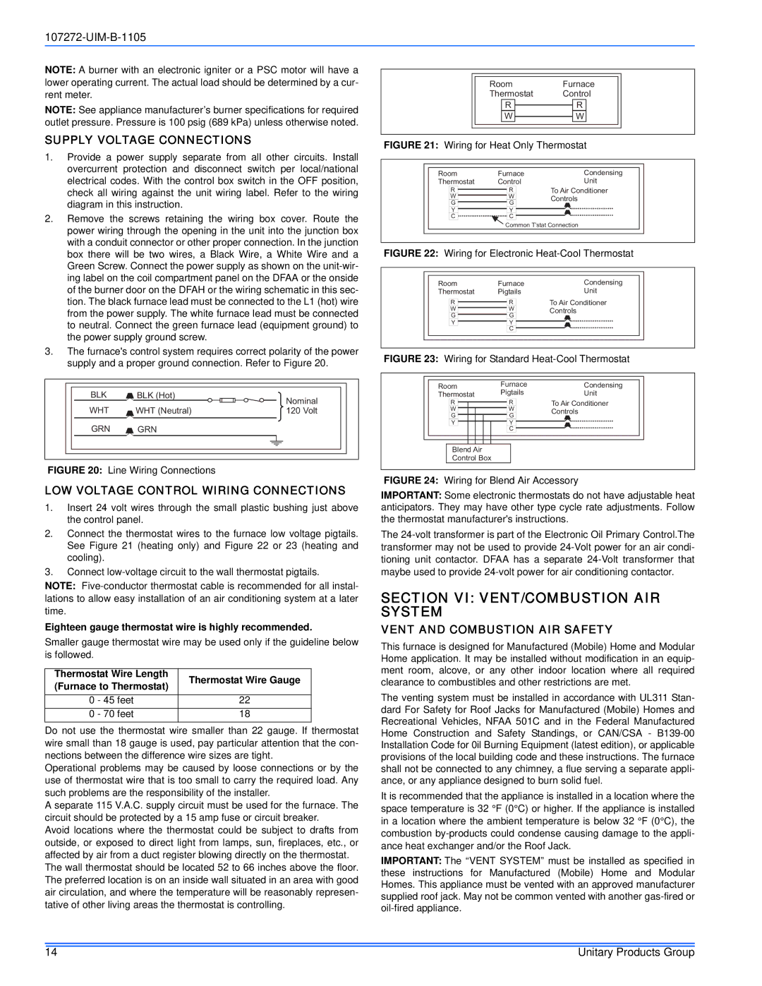
FIGURE 21: Wiring for Heat Only Thermostat
Room | Furnace | Condensing | |
Thermostat | Control | Unit | |
R | R | To Air Conditioner | |
W | W | Controls | |
G | G | ||
| |||
Y | Y |
| |
C | C |
| |
| Common T’stat Connection | ||
FIGURE 22: Wiring for Electronic Heat-Cool Thermostat
Room | Furnace | Condensing | |
Thermostat | Pigtails | Unit | |
R | R | To Air Conditioner | |
W | W | Controls | |
G | G | ||
| |||
Y | Y |
| |
| C |
|
FIGURE 23: Wiring for Standard Heat-Cool Thermostat
Room | Furnace | Condensing |
Thermostat | Pigtails | Unit |
R | R | To Air Conditioner | |
W | W | Controls | |
G | G | ||
| |||
Y | Y |
| |
| C |
|
Blend Air
Control Box
FIGURE 24: Wiring for Blend Air Accessory
IMPORTANT: Some electronic thermostats do not have adjustable heat anticipators. They may have other type cycle rate adjustments. Follow the thermostat manufacturer's instructions.
The
SECTION VI: VENT/COMBUSTION AIR SYSTEM
VENT AND COMBUSTION AIR SAFETY
This furnace is designed for Manufactured (Mobile) Home and Modular Home application. It may be installed without modification in an equip- ment room, alcove, or any other indoor location where all required clearance to combustibles and other restrictions are met.
The venting system must be installed in accordance with UL311 Stan- dard For Safety for Roof Jacks for Manufactured (Mobile) Homes and Recreational Vehicles, NFAA 501C and in the Federal Manufactured Home Construction and Safety Standings, or CAN/CSA -
It is recommended that the appliance is installed in a location where the space temperature is 32 °F (0°C) or higher. If the appliance is installed in a location where the ambient temperature is below 32 °F (0°C), the combustion
IMPORTANT: The “VENT SYSTEM” must be installed as specified in these instructions for Manufactured (Mobile) Home and Modular Homes. This appliance must be vented with an approved manufacturer supplied roof jack. May not be common vented with another
14 | Unitary Products Group |