OPERATION
VARIABLE SPEED
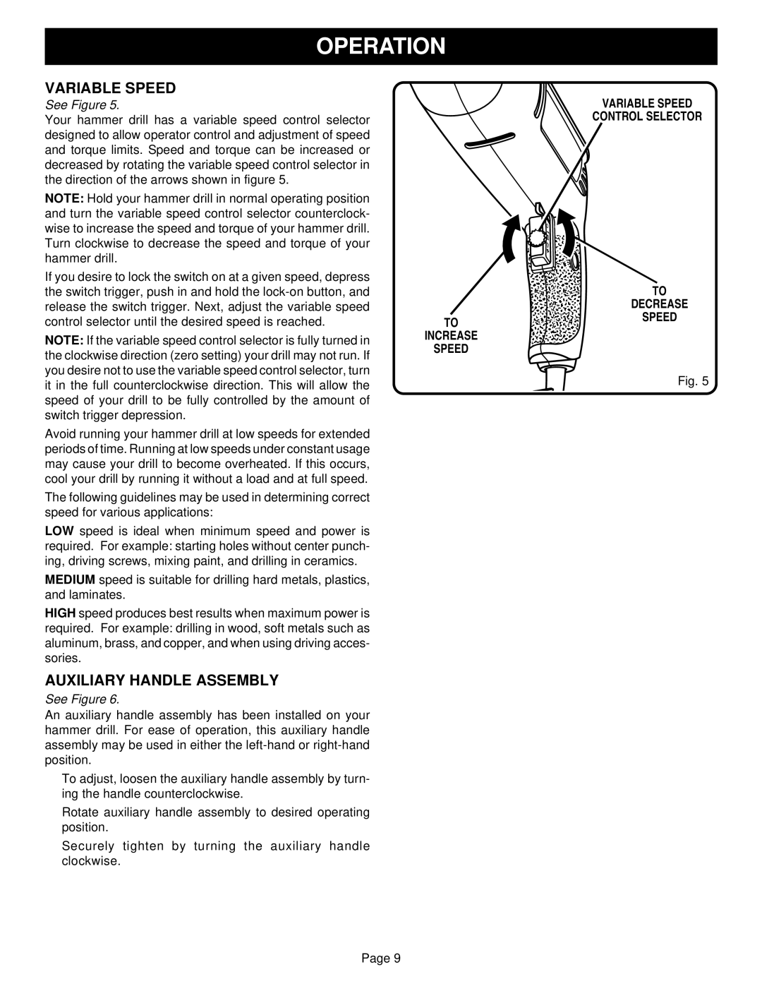
See Figure 5.
Your hammer drill has a variable speed control selector designed to allow operator control and adjustment of speed and torque limits. Speed and torque can be increased or decreased by rotating the variable speed control selector in the direction of the arrows shown in figure 5.
NOTE: Hold your hammer drill in normal operating position and turn the variable speed control selector counterclock- wise to increase the speed and torque of your hammer drill. Turn clockwise to decrease the speed and torque of your hammer drill.
If you desire to lock the switch on at a given speed, depress the switch trigger, push in and hold the
VARIABLE SPEED
CONTROL SELECTOR
TO
DECREASE
control selector until the desired speed is reached.
TO
SPEED
NOTE: If the variable speed control selector is fully turned in the clockwise direction (zero setting) your drill may not run. If you desire not to use the variable speed control selector, turn it in the full counterclockwise direction. This will allow the speed of your drill to be fully controlled by the amount of switch trigger depression.
Avoid running your hammer drill at low speeds for extended periods of time. Running at low speeds under constant usage may cause your drill to become overheated. If this occurs, cool your drill by running it without a load and at full speed.
The following guidelines may be used in determining correct speed for various applications:
LOW speed is ideal when minimum speed and power is required. For example: starting holes without center punch- ing, driving screws, mixing paint, and drilling in ceramics.
MEDIUM speed is suitable for drilling hard metals, plastics, and laminates.
HIGH speed produces best results when maximum power is required. For example: drilling in wood, soft metals such as aluminum, brass, and copper, and when using driving acces- sories.
AUXILIARY HANDLE ASSEMBLY
See Figure 6.
An auxiliary handle assembly has been installed on your hammer drill. For ease of operation, this auxiliary handle assembly may be used in either the
■To adjust, loosen the auxiliary handle assembly by turn- ing the handle counterclockwise.
■Rotate auxiliary handle assembly to desired operating position.
■Securely tighten by turning the auxiliary handle clockwise.
INCREASE
SPEED
Fig. 5
Page 9