OPERATION
TWO-SPEED GEAR TRAIN
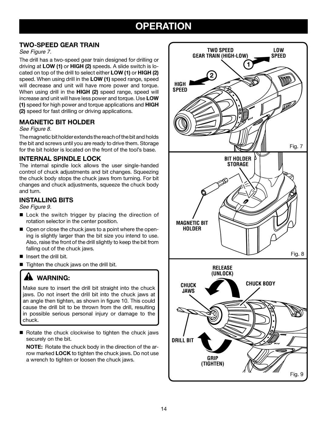
See Figure 7.
The drill has a
(1)speed for high power and torque applications and HIGH
(2)speed for fast drilling or driving applications.
MAGNETIC BIT HOLDER
See Figure 8.
The magnetic bit holder extends the reach of the bit and holds the bit and screws until you are ready to drive them. Storage for the bit holder is located on the front of the tool’s base.
INTERNAL SPINDLE LOCK
The internal spindle lock allows the user
INSTALLING BITS
See Figure 9.
n Lock the switch trigger by placing the direction of rotation selector in the center position.
nOpen or close the chuck jaws to a point where the open- ing is slightly larger than the bit size you intend to use. Also, raise the front of the drill slightly to keep the bit from falling out of the chuck jaws.
nInsert the drill bit.
nTighten the chuck jaws on the drill bit.
WARNING:
Make sure to insert the drill bit straight into the chuck jaws. Do not insert the drill bit into the chuck jaws at an angle then tighten, as shown in figure 10. This could cause the drill bit to be thrown from the drill, resulting in possible serious personal injury or damage to the chuck.
nRotate the chuck clockwise to tighten the chuck jaws securely on the bit.
NOTE: Rotate the chuck body in the direction of the ar- row marked LOCK to tighten the chuck jaws. Do not use a wrench to tighten or loosen the chuck jaws.
TWO SPEED | LOW |
GEAR TRAIN | SPEED |
1 |
|
2 |
|
HIGH |
|
SPEED |
|
Fig. 7
BIT HOLDER 


STORAGE
MAGNETIC BIT
HOLDER
Fig. 8
RELEASE (UNLOCK)
CHUCK | CHUCK BODY |
JAWS |
|
DRILL BIT
GRIP
(TIGHTEN)
Fig. 9
14