ASSEMBLY
ATTACHING THE SHOULDER HARNESS - ZR30004
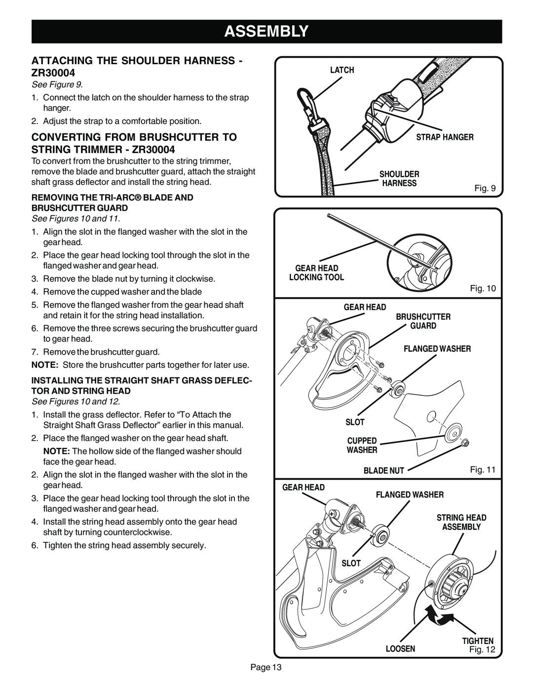
See Figure 9.
1.Connect the latch on the shoulder harness to the strap hanger.
2.Adjust the strap to a comfortable position.
CONVERTING FROM BRUSHCUTTER TO STRING TRIMMER - ZR30004
To convert from the brushcutter to the string trimmer, remove the blade and brushcutter guard, attach the straight
LATCH
STRAP HANGER
SHOULDER
shaft grass deflector and install the string head.
REMOVING THE TRI-ARC® BLADE AND
BRUSHCUTTER GUARD
See Figures 10 and 11.
1. | Align the slot in the flanged washer with the slot in the |
| gear head. |
2. | Place the gear head locking tool through the slot in the |
| flanged washer and gear head. |
3. | Remove the blade nut by turning it clockwise. |
HARNESS
GEAR HEAD
LOCKING TOOL
Fig. 9
4. | Remove the cupped washer and the blade |
5. | Remove the flanged washer from the gear head shaft |
| and retain it for the string head installation. |
6. | Remove the three screws securing the brushcutter guard |
| to gear head. |
7. | Remove the brushcutter guard. |
NOTE: Store the brushcutter parts together for later use.
INSTALLING THE STRAIGHT SHAFT GRASS DEFLEC- TOR AND STRING HEAD
See Figures 10 and 12.
1.Install the grass deflector. Refer to “To Attach the Straight Shaft Grass Deflector” earlier in this manual.
2.Place the flanged washer on the gear head shaft.
NOTE: The hollow side of the flanged washer should face the gear head.
2.Align the slot in the flanged washer with the slot in the gear head.
3.Place the gear head locking tool through the slot in the flanged washer and gear head.
4.Install the string head assembly onto the gear head shaft by turning counterclockwise.
6. Tighten the string head assembly securely.
Fig. 10
GEAR HEAD
BRUSHCUTTER
GUARD
FLANGED WASHER
SLOT
CUPPED 
WASHER
BLADE NUT | Fig. 11 |
|
|
GEAR HEAD
FLANGED WASHER
STRING HEAD
ASSEMBLY
SLOT
LOOSEN | TIGHTEN |
Fig. 12 |
Page 13
