Guided Tour - Mono and Stereo Channels
1 |
|
2 | 1 |
3 |
|
10 |
|
0 |
|
+4 | |
TRIM |
|
0 |
|
+15 | |
HIGH |
|
0 |
|
+15 | |
MID |
|
0 |
|
+15 | |
LOW |
|
| 0 |
−∞ | +10 |
AUX 1 | |
| 0 |
−∞ | +10 |
AUX 2 | |
L | R |
PAN |
|
PEAK |
|
0 |
|
−∞ | +15 |
GAIN |
|
1 |
|
1
2
3
4
5
6
8
9
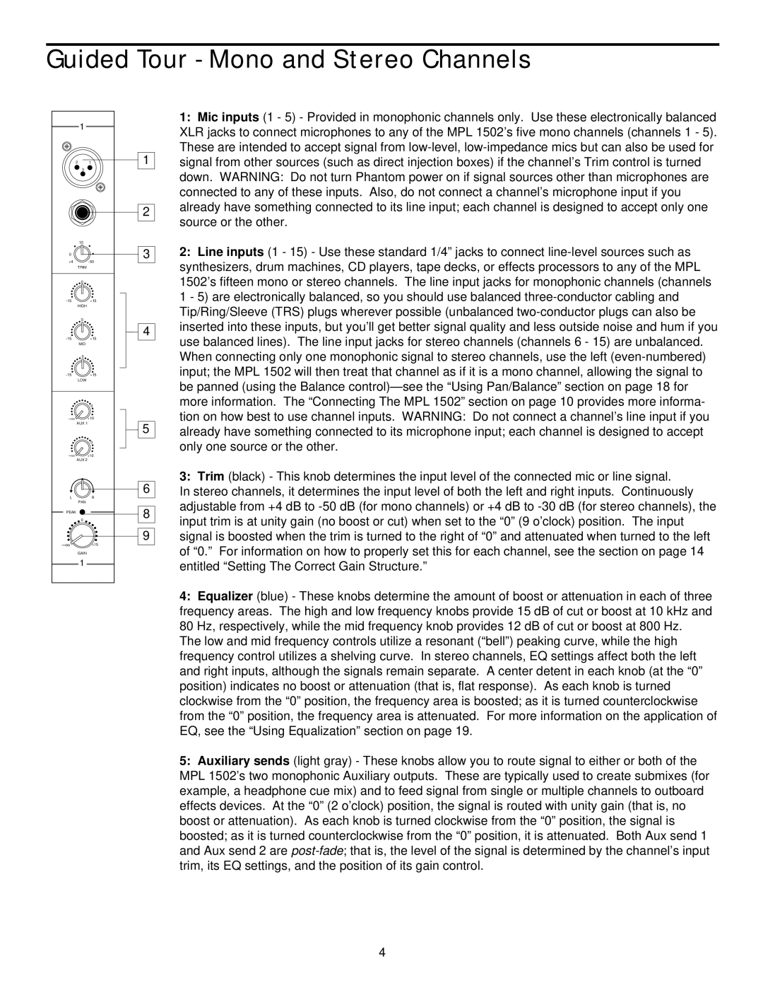
1:Mic inputs (1 - 5) - Provided in monophonic channels only. Use these electronically balanced XLR jacks to connect microphones to any of the MPL 1502’s five mono channels (channels 1 - 5). These are intended to accept signal from
2:Line inputs (1 - 15) - Use these standard 1/4” jacks to connect
3:Trim (black) - This knob determines the input level of the connected mic or line signal.
In stereo channels, it determines the input level of both the left and right inputs. Continuously adjustable from +4 dB to
4:Equalizer (blue) - These knobs determine the amount of boost or attenuation in each of three frequency areas. The high and low frequency knobs provide 15 dB of cut or boost at 10 kHz and 80 Hz, respectively, while the mid frequency knob provides 12 dB of cut or boost at 800 Hz.
The low and mid frequency controls utilize a resonant (“bell”) peaking curve, while the high frequency control utilizes a shelving curve. In stereo channels, EQ settings affect both the left and right inputs, although the signals remain separate. A center detent in each knob (at the “0” position) indicates no boost or attenuation (that is, flat response). As each knob is turned clockwise from the “0” position, the frequency area is boosted; as it is turned counterclockwise from the “0” position, the frequency area is attenuated. For more information on the application of EQ, see the “Using Equalization” section on page 19.
5:Auxiliary sends (light gray) - These knobs allow you to route signal to either or both of the MPL 1502’s two monophonic Auxiliary outputs. These are typically used to create submixes (for example, a headphone cue mix) and to feed signal from single or multiple channels to outboard effects devices. At the “0” (2 o’clock) position, the signal is routed with unity gain (that is, no boost or attenuation). As each knob is turned clockwise from the “0” position, the signal is boosted; as it is turned counterclockwise from the “0” position, it is attenuated. Both Aux send 1 and Aux send 2 are
4
