Guided Tour - Main Section
1
2
3
4
6
| MPL 1502 |
| |||||
15 CHANNEL STEREO MIXER | |||||||
LEFT | 0 | +2 | +6 | ||||
|
|
|
|
|
|
| |
RIGHT | 0 | +2 | +6 | ||||
| |||||||
PHANTOM |
|
| POWER |
| |||
|
| TAPE IN |
|
|
|
| |
|
| ON |
|
|
|
|
|
|
| OFF |
|
|
|
|
|
| CHANNEL 14 / 15 |
|
|
| |||
| 0 |
|
|
|
|
|
|
−∞ | +20 |
|
| L |
| R |
|
AUX 1 LEVEL |
|
| BALANCE |
| |||
| 0 |
|
|
|
|
|
|
−∞ | +20 |
|
| L |
| R |
|
AUX 2 LEVEL |
|
| BALANCE |
| |||
0 | 10 |
|
|
|
|
|
|
HEADPHONE |
|
|
|
|
|
| |
LEVEL |
|
|
|
|
|
|
|
|
|
|
|
| 0 |
|
|
|
|
| −∞ |
|
| +15 |
|
|
|
|
| MAIN |
| ||
5
7
8
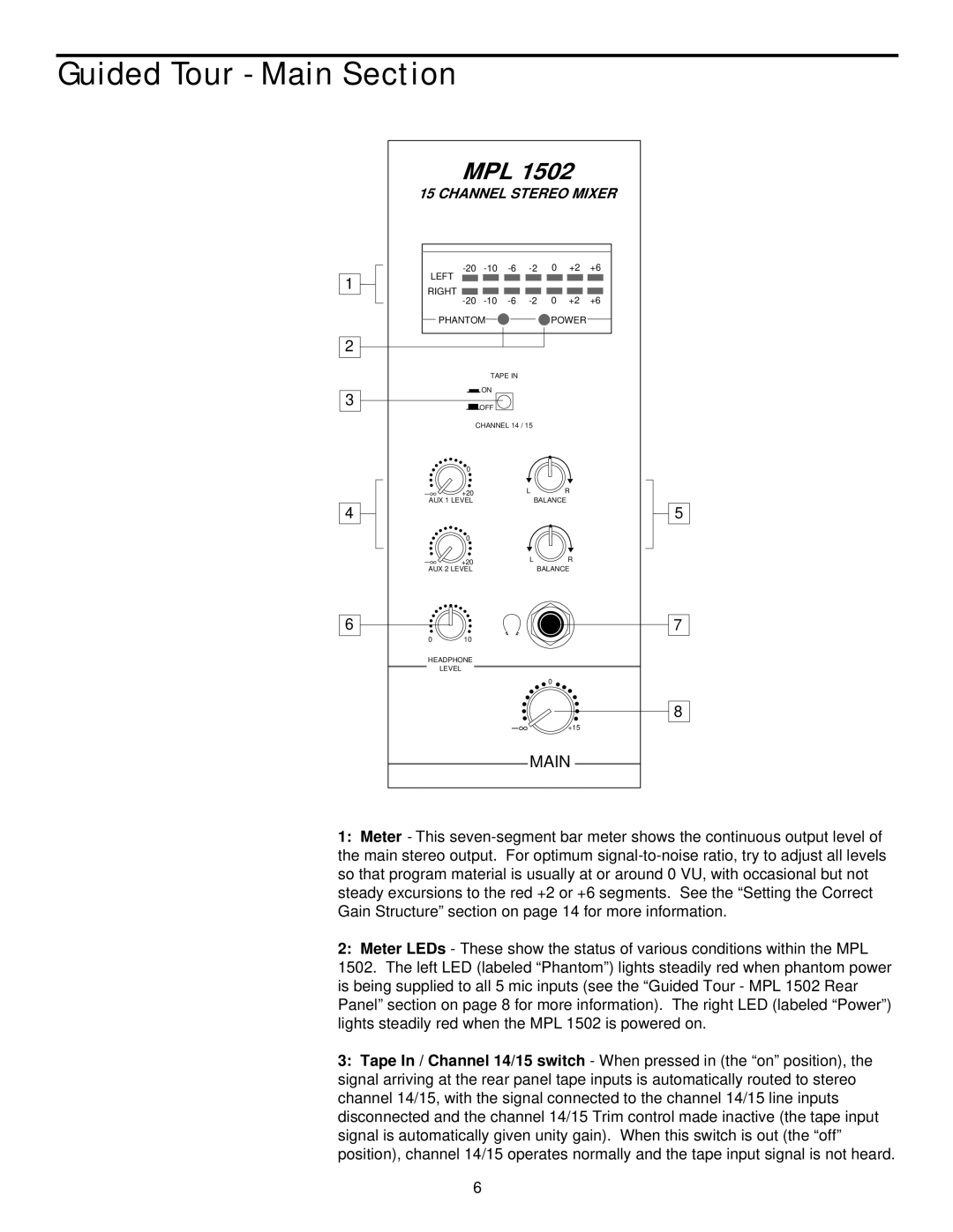
1:Meter - This
2:Meter LEDs - These show the status of various conditions within the MPL
1502. The left LED (labeled “Phantom”) lights steadily red when phantom power is being supplied to all 5 mic inputs (see the “Guided Tour - MPL 1502 Rear Panel” section on page 8 for more information). The right LED (labeled “Power”) lights steadily red when the MPL 1502 is powered on.
3:Tape In / Channel 14/15 switch - When pressed in (the “on” position), the signal arriving at the rear panel tape inputs is automatically routed to stereo channel 14/15, with the signal connected to the channel 14/15 line inputs disconnected and the channel 14/15 Trim control made inactive (the tape input signal is automatically given unity gain). When this switch is out (the “off” position), channel 14/15 operates normally and the tape input signal is not heard.
6