Manuals
/
Samsung
/
Computer Equipment
/
Computer Monitor
Samsung
943NWX
service manual
Inverter Part
Models:
943NWX
943NW
1
27
46
46
Download
46 pages
25.57 Kb
24
25
26
27
28
29
30
31
Troubleshooting
Specification
Install
Parts list
Schematic Diagram
Error Examples and Actions
Accessories
Connector Functions
Disassembly and Assembly
Adjustment
Page 27
Image 27
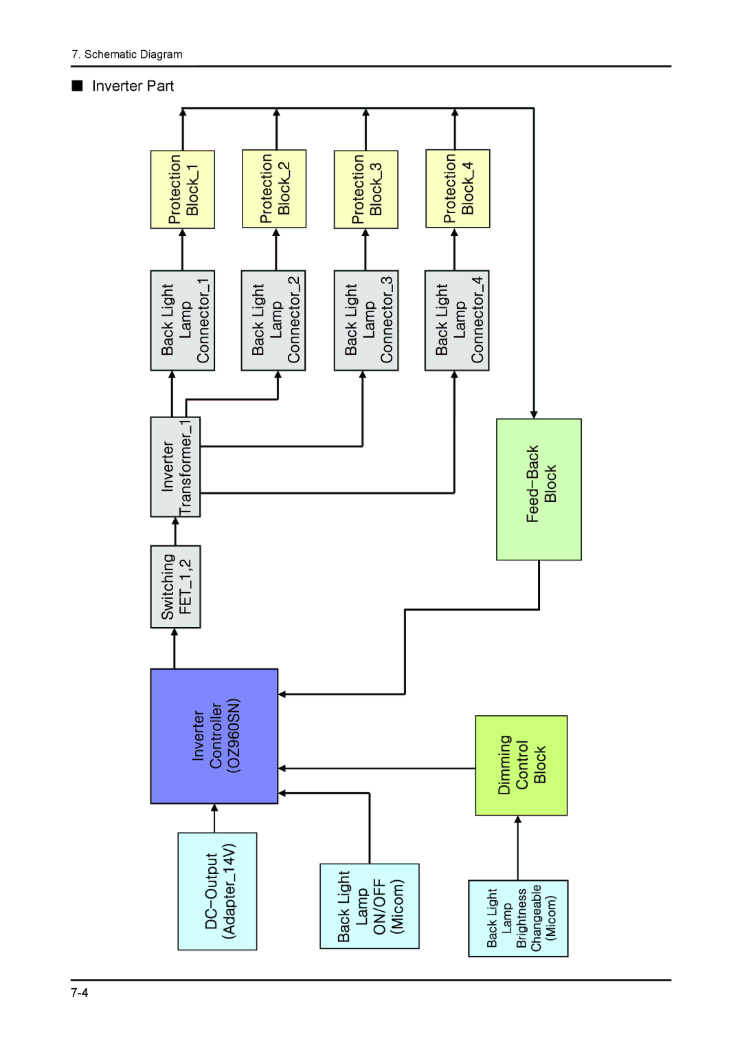
7. Schematic Diagram
Inverter Part
7-4
Page 26
Page 28
Page 27
Image 27
Page 26
Page 28
Contents
LCD-Monitor
Contents
CIS
Simple Stand Disassembly
Disassembly and Assembly
Description Photo
Description Photo
Has Stand Disassembly
Simple Stand Exploded View LS19MYNKFZ/XBM
Exploded View & Part List
1. LS19MYNKFZ/XBM Parts List 943NWX
Service Bom SA Service AVAILABLE, SNA Service not Available
LS19MYNKFZ/XBM Parts List
PCB
IC-EEPROMS-24CS08AFJ-TB
Exploded View & Part List
Clamper CORE-WIREALL MODEL,NYLON
COVER-STAND FRONTLS19MYW,HIPS HB,BK26,S
Servicing the LCD Monitor
Precautions
Safety Precautions
Product Safety Notices
Servicing Precautions
Static Electricity Precautions
General Servicing Precautions
Installation Precautions
Memo
Feature & Specifications
Product specifications
Magic Color Color Effect Magic Bright3 Magic Tune Premium
Spec Comparison to the Old Models
Accessories Sold separately
Accessories
Memo
Circuit Descriptions
Schematic Diagram
Schematic Diagrams Scaler Part
Schematic Diagrams Power Flowchart
SE717M-LF
Schematic Diagrams IP Board
Inverter Part
Schematic Diagrams Main PBA
Troubleshooting
Troubleshooting
When the Power Does Not Turn On
Circuit diagrams when the power does not turn on
When the screen is blank Analog
When a blank screen is displayed Analog
Waveforms when no screen is displayed Analog
Error Examples and Actions
Service Adjustment Conditions
Adjustment
Checking the Code Version
Service Function Specifications
When replacing the panel
Inputting the DDC Data
Inputting the MCU Data
Page
Memo
Wiring Diagram Main Board
Wiring Diagram
SE717M-LF
Wiring Diagram IP Board
Cables
Connector Functions
Memo
Top
Page
Image
Contents