TROUBLE SHOOTING
![]() WARNING
WARNING
To avoid risk of electrical shock, personal injury or death; disconnect power to dryer before servicing, unless testing requires power.
COMPONENT TESTING PROCEDURES
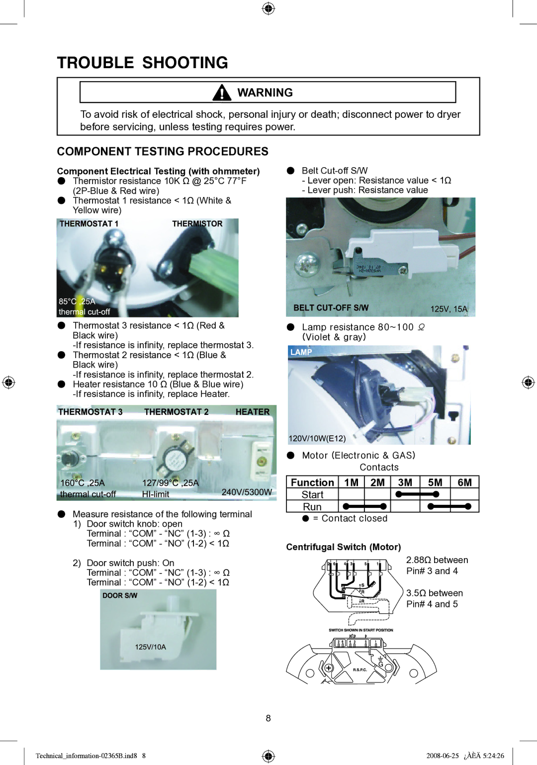
Component Electrical Testing (with ohmmeter) | ● Belt |
● Thermistor resistance 10K Ω @ 25°C 77°F | - Lever open: Resistance value < 1Ω |
- Lever push: Resistance value | |
● Thermostat 1 resistance < 1Ω (White & |
|
Yellow wire) |
|
●Thermostat 3 resistance < 1Ω (Red &
Black wire)
●Thermostat 2 resistance < 1Ω (Blue &
Black wire)
●Heater resistance 10 Ω (Blue & Blue wire)
●Measure resistance of the following terminal
1)Door switch knob: open
Terminal : “COM” - “NC”
Terminal : “COM” - “NO”
2)Door switch push: On
Terminal : “COM” - “NC”
Terminal : “COM” - “NO”
●Lamp resistance 80~100 Ω (Violet & gray)
●Motor (Electronic & GAS) Contacts
Function 1M 2M 3M 5M 6M
Start
Run
![]() = Contact closed
= Contact closed
Centrifugal Switch (Motor)
2.88Ω between Pin# 3 and 4
3.5Ω between Pin# 4 and 5