PDP-TELEVISION
Warranty
User Instructions
Screen Image retention
Cell Defect
Power Cord
Scart Cable Speaker Wire
Owner’s Instructions
Video Cable DVI Cable
Contents
Symbols
Contents
Your New Plasma Display Panel
Your New Plasma Display Panel
Actual configuration on your PDP may be different
For further details about connection, refer to pages 55~59
Infrared Remote Control
Assembling the Stand-Base
Inserting the Batteries in the Remote Control
Angle of the PDP can be up to 15 degrees left/right
Installing the Display on the Wall Attachment Panel
Wall Mount Bracket Plastic Hanger
Connecting External Devices to the PDP
Connecting to an Aerial or Cable Television Network
Connecting a Satellite Receiver or Decoder
Using a Coaxial cable
Rear of the PDP
Switching On and Off
Placing in Standby Mode
Refer to page 64 for further instructions on plug wiring
Mains lead is attached to the rear of your PDP
Becoming Familiar with the Remote Control
Remote control is used mainly to
Change channels and adjust the volume
Display the on-screen menu system
Setting Up Your Remote Control
Plug & Play Feature
To start the search, press the Enter button
If you want to reset this feature
Choosing Your Language
Storing Channels Automatically
See
Storing ChannelsManually
You wish to identify
Channel mode
Skipping unwanted channels
Skipping Unwanted Channels
Result The Edit menu is displayed
Sorting the Stored Channels
Assigning Names to Channels
Using the LNA Low Noise Amplifier Feature
Activating the Child Lock
Activating the child lock
Displaying Information
Changing the Picture Standard
Adjusting the Picture Settings
Custom Options available in PC, DVI Mode Contrast
Adjusting the Picture Settings PC or DVI Mode
Custom PC mode only Colour1 Colour2 Colour3
Setting the Picture PC Mode
Preset to the PC mode by using the Source button
Setting the Picture PC Mode
Using the Fine Tune
If reception is weak, you can fine tune a channel manually
Viewing the Channel Scan Picture
Freezing the Current Picture
Result Main menu is displayed
Displayed
PC to DVI Mode
Positioning and Sizing the screen using Zoom
Selecting the Picture Size
Selecting the Film Mode
DNIeTM Digital Natural Image engine
Setting the Blue Screen
Setting the Melody Sound
Table of PIP Settings
Viewing the Picture In Picture PIP
Result The sources are displayed in the following order
Result The main picture and sub picture are interchanged
Easy functions of remote control
Buttons Feature
Using the Digital NR Digital Noise Reduction Feature
Selecting the Fan
Changing the Sound Standard
Standard Music Movie Speech Custom
Adjusting the Sound Settings
Adjusting the Volume Automatically
Setting the TruSurround XT
Selecting the Internal Mute
Selecting the Sound Mode depending on the model
Setting the Sleep Timer
Setting and Displaying the Current Time
Switching the Television On and Off Automatically
Absent Power Off
Viewing an External Signal Source
AV1 AV2 AV3
Redirecting an Input to the External Output
Teletext Feature
Contents
Displaying the Teletext Information
Press the TTX/MIX button again
Selecting Display Options
To display Press
Selecting a Teletext
TeleWeb Feature Option
Using the TeleWeb Menu after Displaying the TeleWeb Option
Bookmarking the current
Entering the bookmarked URL
Opening the Home
ButtonFunction TeleWeb
Connecting to the External Devices
Input/Output Specification
Rear of the TV
Input
Connecting to the S-Video Input
Rear of the TV Side of the TV
Connecting to the DVI Input
Connecting to the PC Input
Connecting to the Component Input
Connecting the Home Theater System
Connecting and Using the Home Theater System
To Display the DVD Home Theater
How to Install Speakers
This speaker installation guide is for the 5040 Model
How to Assemble the SpeakersWall Mount
Correct settings for these two variables are
Setting up Your PC Software Windows only
Shown at left is a typical screen for Display dialog box
Video Signal Resolution Vertical Horizontal
Input Mode PC/DVI
FrequencyHz
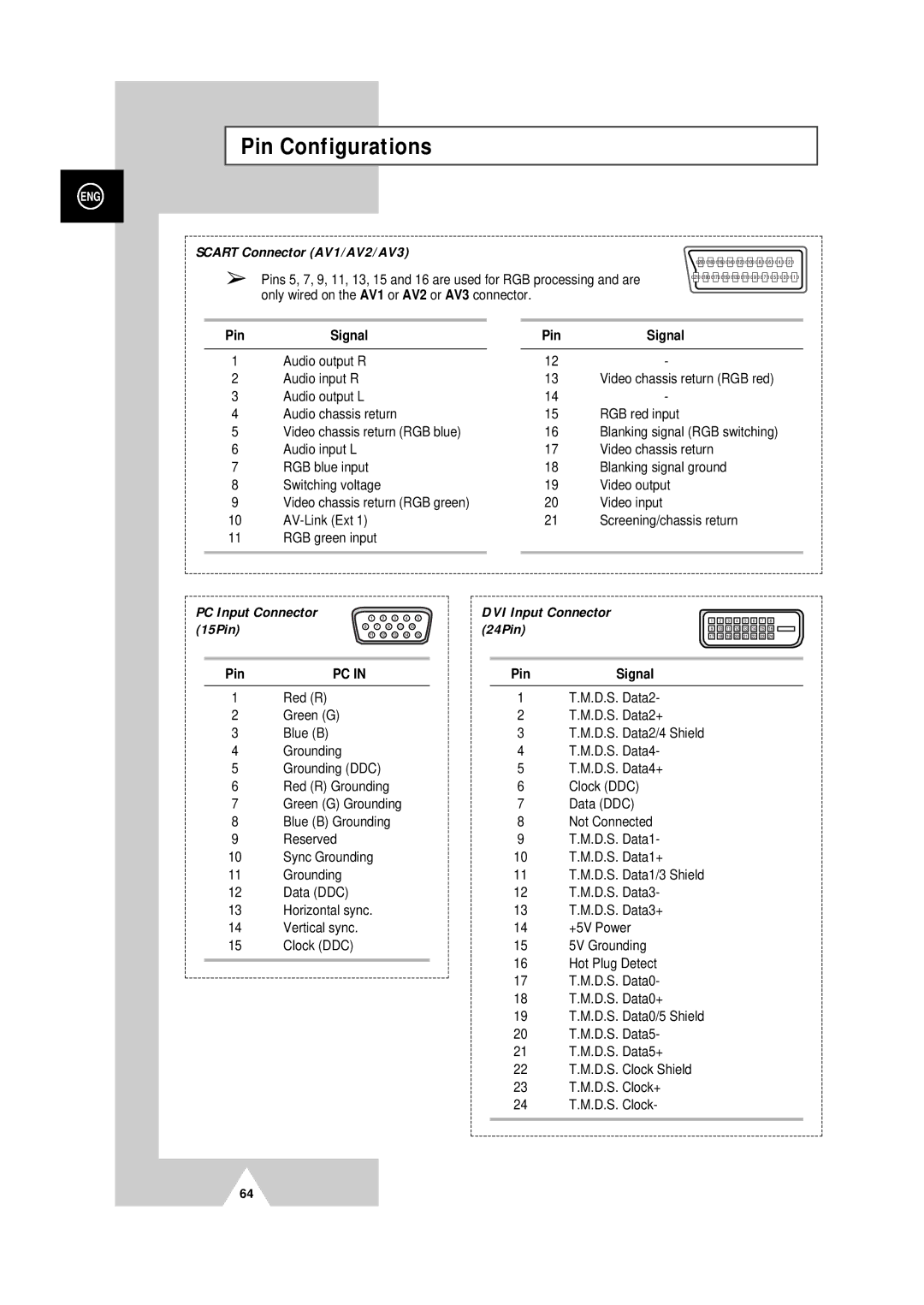
Pin Configurations
Power button
Check the picture contrast and brightness settings
Check the volume
Normal picture but no sound Check the volume
Programming the Remote Control for Other Components
Wamer amex
Programming the Remote Control for Other Components
040, 047, 050, 052, 060, 063, 065, 066, 067
After Sales Service