Installation


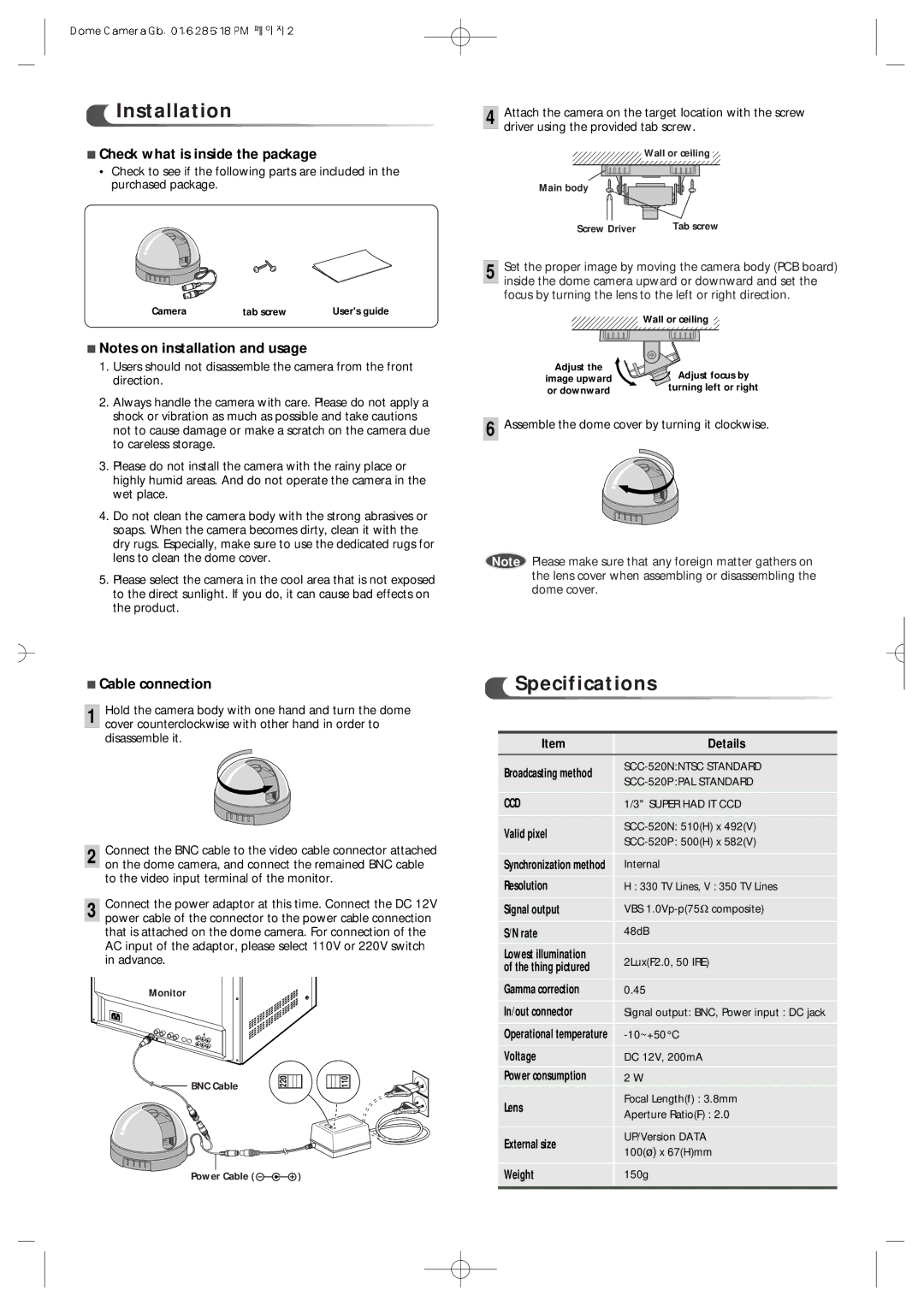
■Check what is inside the package
•Check to see if the following parts are included in the purchased package.
Camera | tab screw | User's guide |
■Notes on installation and usage
1.Users should not disassemble the camera from the front direction.
2.Always handle the camera with care. Please do not apply a shock or vibration as much as possible and take cautions not to cause damage or make a scratch on the camera due to careless storage.
3.Please do not install the camera with the rainy place or highly humid areas. And do not operate the camera in the wet place.
4.Do not clean the camera body with the strong abrasives or soaps. When the camera becomes dirty, clean it with the dry rugs. Especially, make sure to use the dedicated rugs for lens to clean the dome cover.
5.Please select the camera in the cool area that is not exposed to the direct sunlight. If you do, it can cause bad effects on the product.
4 Attach the camera on the target location with the screw driver using the provided tab screw.
Wall or ceiling
Main body
Screw Driver | Tab screw |
5 Set the proper image by moving the camera body (PCB board) inside the dome camera upward or downward and set the focus by turning the lens to the left or right direction.
Wall or ceiling
Adjust the | Adjust focus by | |
image upward | ||
turning left or right | ||
or downward | ||
|
6 Assemble the dome cover by turning it clockwise.
Note Please make sure that any foreign matter gathers on the lens cover when assembling or disassembling the dome cover.
■Cable connection
1Hold the camera body with one hand and turn the dome cover counterclockwise with other hand in order to disassemble it.
2 Connect the BNC cable to the video cable connector attached on the dome camera, and connect the remained BNC cable to the video input terminal of the monitor.
3 Connect the power adaptor at this time. Connect the DC 12V power cable of the connector to the power cable connection that is attached on the dome camera. For connection of the AC input of the adaptor, please select 110V or 220V switch in advance.
Monitor
BNC Cable | 220 | 110 |
|
|
Power Cable ( ![]()
![]()
![]()
![]() )
)


 Specifications


Item | Details | |
Broadcasting method | ||
| ||
CCD | 1/3" SUPER HAD IT CCD | |
Valid pixel | ||
| ||
Synchronization method | Internal | |
Resolution | H : 330 TV Lines, V : 350 TV Lines | |
Signal output | VBS | |
S/N rate | 48dB | |
Lowest illumination | 2Lux(F2.0, 50 IRE) | |
of the thing pictured | ||
| ||
Gamma correction | 0.45 | |
In/out connector | Signal output: BNC, Power input : DC jack | |
Operational temperature | ||
Voltage | DC 12V, 200mA | |
Power consumption | 2 W | |
Lens | Focal Length(f) : 3.8mm | |
Aperture Ratio(F) : 2.0 | ||
| ||
External size | UP/Version DATA | |
100(ø) x 67(H)mm | ||
| ||
Weight | 150g | |
|
|