Introduction
❺
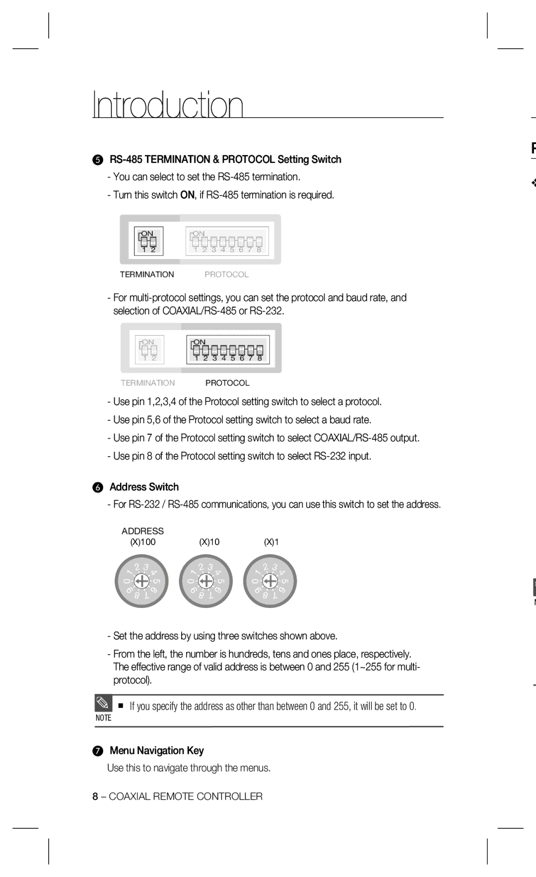
-You can select to set the
-Turn this switch ON, if
ONON
1 | 2 | 1 | 2 | 3 | 4 | 5 | 6 | 7 | 8 |
TERMINATION PROTOCOL
-For
ONON
1 | 2 | 1 | 2 | 3 | 4 | 5 | 6 | 7 | 8 |
TERMINATION PROTOCOL
-Use pin 1,2,3,4 of the Protocol setting switch to select a protocol.
-Use pin 5,6 of the Protocol setting switch to select a baud rate.
-Use pin 7 of the Protocol setting switch to select
-Use pin 8 of the Protocol setting switch to select
❻Address Switch
-For
ADDRESS
(X)100(X)10(X)1
1 | 2 | 3 |
| 1 | 2 | 3 |
| 1 | 2 | 3 |
|
| 4 |
| 4 |
| 4 | ||||||
0 |
|
| 5 | 0 |
|
| 5 | 0 |
|
| 5 |
9 | 7 | 6 | 9 | 7 | 6 | 9 | 7 | 6 | |||
| 8 |
|
| 8 |
|
| 8 |
| |||
-Set the address by using three switches shown above.
-From the left, the number is hundreds, tens and ones place, respectively. The effective range of valid address is between 0 and 255 (1~255 for multi- protocol).
If you specify the address as other than between 0 and 255, it will be set to 0.
NOTE
❼Menu Navigation Key
Use this to navigate through the menus.
P
❖
N
8 – COAXIAL REMOTE CONTROLLER
