8. BLDC MOTOR Operation Circuit
1)Operate description of BLDC MOTOR First, if FAN became before operate condition of FANMOTOR, condition of in the temp. are high temp. more than FAN of recently institutionn NOTCH is operated condition.
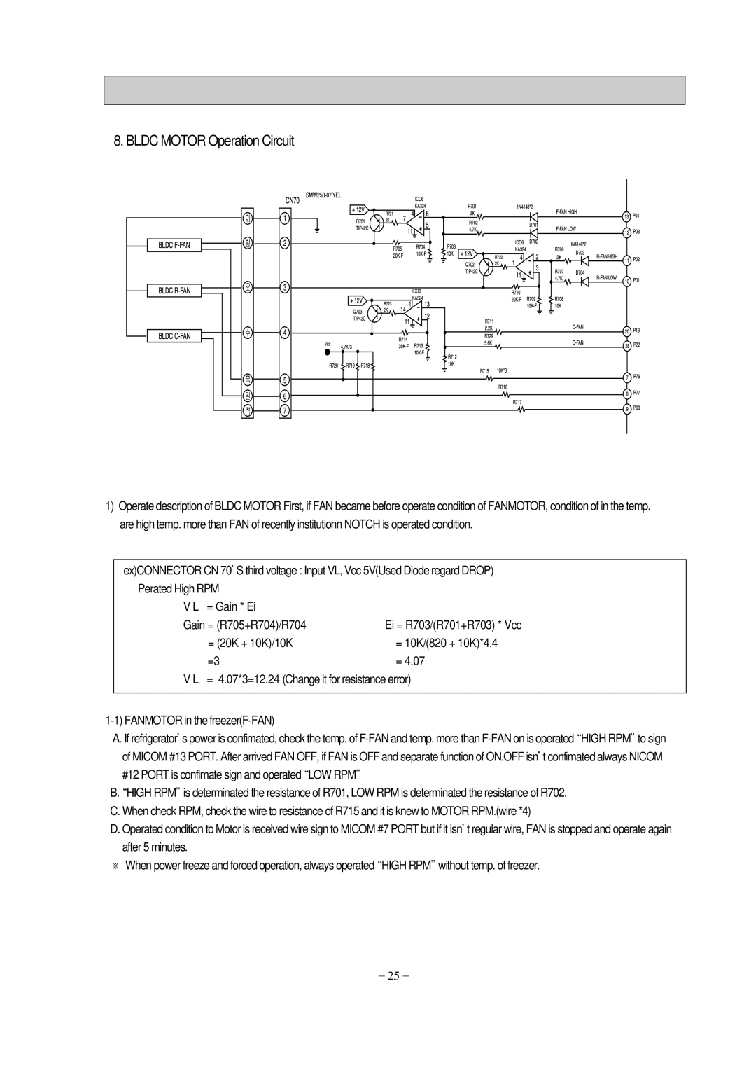
ex)CONNECTOR CN 70’S third voltage : Input VL, Vcc 5V(Used Diode regard DROP)
Perated High RPM |
|
V L = Gain * Ei |
|
Gain = (R705+R704)/R704 | Ei = R703/(R701+R703) * Vcc |
= (20K + 10K)/10K | = 10K/(820 + 10K)*4.4 |
=3 | = 4.07 |
V L = 4.07*3=12.24 (Change it for resistance error)
A. If refrigerator’s power is confimated, check the temp. of
B“. HIGH RPM”is determinated the resistance of R701, LOW RPM is determinated the resistance of R702. C. When check RPM, check the wire to resistance of R715 and it is knew to MOTOR RPM.(wire *4)
D. Operated condition to Motor is received wire sign to MICOM #7 PORT but if it isn’t regular wire, FAN is stopped and operate again after 5 minutes.
※When power freeze and forced operation, always operated“HIGH RPM”without temp. of freezer.
-25-