REFRIGERATOR
CONTENTS
Model SR-61KTC/SR-61NMC SR-65KTC/SR-65NMC
SR-69NMC
1. Product specifications
Prohibition
Description of symbols
2.Safety precautions and warnings
Warning/Caution
Reted
Prohibition
Prohibition
Prohibition
3. ELECTRIC PARTS STANDARD
REFRIGERATION PARTS
TEMPERATURE DEFROST
ELECTRIC PARTS
4-1.Electronic modeSR-61KTC,65KTCT
4. Electric diagram
4-2SEMI BASIC SR-61NMC,65NMC, 69NMC
5. Cool Air Circulation
SR-69NMC
6. FUNCTIONS AND DIRECTIONS
MODEL
SR-61NMC
DID CASE
6-2.THE NAME OF EACH PARTS AND DISASSEMBLE METHOD
DOOR GUARD
CHILLED ROOM SHELF
-11-
6-3.CYCLE OF FREEZING
7. TEMPERATURE CONTROL AND THE OTHERS
3.Alarming
3Forced operating and defrosting“ Beep”sound
5.SELF DIAGNOSIS
6.LOAD STATUS DISPLAY
7.operating of fan motor
-18-
※Personal Informatin
7-2,SEMI ELECTRONIC MODE
D. TEST FUNCTION
Page
8. CIRCUIT OPERATING THEORY
4.DOOR S/W SENSING PART
5. TEMP·SENSING PART
REMARK
7. COMP AND DEFROSTING HEATER OPERATING
STATES
LOAD
8. BLDC MOTOR Operation Circuit
1-2FAN MOTOR IN THE FREEZER R-FAN
REMARK
9. POTION PART 1PRINCIPIE OF MAVEMENT
NAME
STANDARD
8-2.SEMI ELECTROMAGNETIC 9-1.POWER PART
9-3.RESET CIRCUIT PART
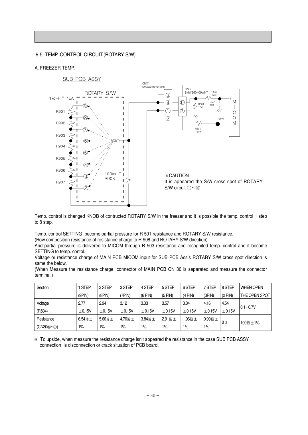
9-5.TEMP. CONTROL CIRCUIT.ROTARY S/W
-31-
B. REFRIGERATOR TEMP ※ CAUTION
It is appeared the S/W cross spot of ROTARY
S/Wcircuit ①~⑩
-32-
6. ELECRICAL LOAD SIGNAL LAMP CONTROL PART
B. MOVEMENT PRINCIPAL
-34-
※PERSANAL INFORMA
Remark
MODEL NAME
1.ELECTRICAL SR-61KTC,65KTC
9.Diagnosis of disorder and method of repair
1.Check the power of consent and power code
1.No input Power
-37-
2.Self diagnosis failure
Outer temper ature sensor failure
②Refrigerator temp, sensor failure
-38-
Freezer tem sensor failare
-39-
Freezer’s defrosting sensor failure
3. In case of contiunous alarming REFRENCES
②In case of“Beep-Beep”alarming
4. In case of FAN do not run REFRENCES
-43-
①In case of F-FANdoesn’t run Run the DC voltage
-44-
Forced operation Check CON70 connection check
-45-
the MOTOR Check the MOTOR Chang the MOTOR
-46-
9. Diagnosis of disorder and method of repair
1.When not operating Power
2.SENMI electronic mode SR-61NMC,65NMC
-47-
2. Self diagnosis failure
A. Freezer’s temp·sensor failure
B. Refrigerator’s temp, senser failure
D. Refrigerator’s defrosting sensor failure
C. Freezer’s defrosting sensor failure
-48-
3.In case of FAN in the refrigerator doern’t run
-50-
B. In case of R-FANdo not run ①Check
-51-
②Check ROTARY S/W
Is proper the retrigerators temp·regulator?
4.Badress management of freeze cycle Appearance
-53-
10-1.Freezer comoartmentSR-61KTC,65KTC
10-2.Freezer compartment SR61NMC,65NMC,69NMC
-55-
10-3.Refrigerator Compartment SR-61KTC,65KTC
THERMO-FUSE,ASSY SENSOR-ASSY EVAP-REF
CHASSIC-COMPASSY
CHASSIC-COMPASSY
HING-MID-ASSY
HANDLE-REF,ASSY
10-7.Related Components of DOOR
HANDLE-FRE,ASSY
CASE-DLSPLAY,ASSY
1.Disassemble lathch the top cover of refrigerator
1Remove the back cover lamp and then in door lamp
11-2.Replacement of freezer in door lamp
11-3.Replacement of refrigerator in door lamp
SR-61KTC SR-61/65/69NMC
1 Push the cold storage and remove it
11-4.Disassemble of refrigerator cooling part
2Remove foods and shelves inside the Refrigerator
Remove 2 screws
la tch
Noise protector
Groove for preventing small ice when defrosting
2 holders securing evaporator CABLE TIE FOAM-LEX
Temp·fuse Temp·sensor
1 Pull out the shelf
2 Disassemble DID door with up the iower HINGE
Assembly specifcation of Freezer cooler part
11-6.Disjonting of DID door
1 Disassembie inner lower GROMMET of DID door
Condenser entrance Rubber for Noise protector
11-7.Unit assembly
Motor fan Hot pipe entrance S-PIPE
Pace condenser Pace condenser entrance
Condenser
11-8.Electric box assembly
1.Disconnect the power cord
3.Assembly specification of electric box TEST S/W
FUSE Condenser TRANS-POWER
11-9.Electric box assembly
1.Disconnect the power cord
3.Assembly specification of electric box TEST S/W
EXAMPLE OF PERFECT PACKING
12. PACKING
PACKING OF DOOR AND CABINET
PACKING EXAMPLE OF FRONT SIDE AND BACK SIDE
Circuit way
ORDERING INFORMATION
FEATURES
BLOCK DIAGRAM
13. Main Components Specifacations
ABSOLUTE MAXIMUM RATINGS TA =
ELECTRICAL CHARACTERISTICS KA7805/I
ELECTRICAL CHARACTERISTICS KA7812/I
BLOCK DIAGRAM
3.3V VOLTAGE DETECTOR
FEATURES
Checking low battery
ELECTRICAL CHARACTERISTICS TA =
ABSOLUTE MAXIMUM RATING TA =
ABSOLUTE MAXIMUM RATINGS
FEATURES
2981THRU
8-CHANNELSOURCE DIRVERS
FOR SAFETY OF SERVICE CAUTION
272, Oseon-Dong, Kwangsan-Gu Kwangju-City,Korea
ELECTRONICS
TEL 82-62-950-6810,6811 FAX