INSTALLING THE OUTDOOR UNIT
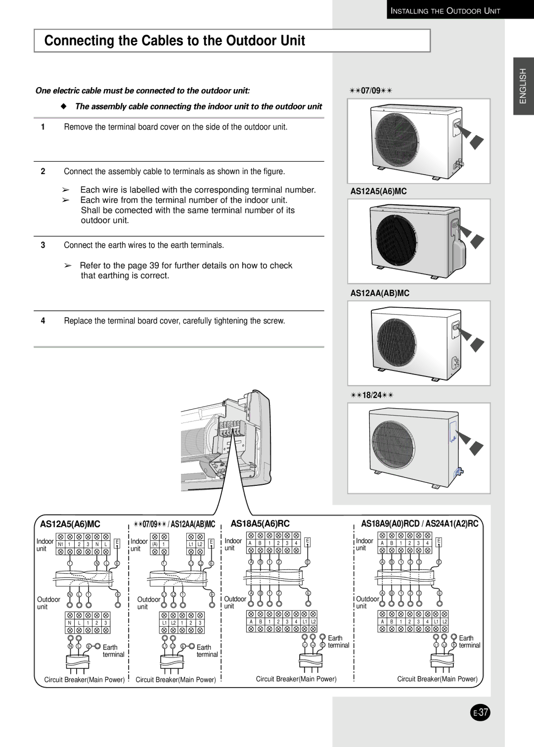
Connecting the Cables to the Outdoor Unit
One electric cable must be connected to the outdoor unit:
◆The assembly cable connecting the indoor unit to the outdoor unit
1Remove the terminal board cover on the side of the outdoor unit.
2Connect the assembly cable to terminals as shown in the figure.
➢Each wire is labelled with the corresponding terminal number.
➢Each wire from the terminal number of the indoor unit. Shall be comected with the same terminal number of its outdoor unit.
3Connect the earth wires to the earth terminals.
➢Refer to the page 39 for further details on how to check that earthing is correct.
✴✴07/09✴✴ | ENGLISH |
| |
AS12A5(A6)MC |
|
AS12AA(AB)MC |
4Replace the terminal board cover, carefully tightening the screw.
AS12A5(A6)MC
Indoor | N1 1 | 2 | 3 | N | L | E |
unit |
|
|
|
|
|
|
| 1 |
|
| N | L | E |
| N | L | 1 |
|
| E |
Outdoor |
|
|
|
|
| |
unit |
|
|
|
|
|
|
| N | L | 1 | 2 | 3 |
|
NL E ![]()
![]() Earth
Earth ![]() terminal
terminal
✴✴07/09✴✴ / AS12AA(AB)MC
Indoor | (A) | 1 |
|
| L1 | L2 | E |
unit |
|
|
|
|
|
|
|
|
| 1 |
|
| L1 | L2 | E |
Outdoor | L1 | L2 | 1 |
|
| E | |
|
|
|
|
|
| ||
unit |
|
|
|
|
|
|
|
|
| L1 | L2 | 1 | 2 | 3 |
|
|
| L1 | L2 | E |
| Earth | |
|
|
|
|
|
| terminal | |
| ✴✴18/24✴✴ |
AS18A5(A6)RC | AS18A9(A0)RCD / AS24A1(A2)RC |
Indoor A B 1 2 3 4 | E | Indoor A B 1 2 3 4 | E |
unit |
| unit |
|
A B 1 2 | E | A B 1 2 3 | E |
A B 1 2 | E | A B 1 2 3 | E |
Outdoor |
| Outdoor |
|
unit |
| unit |
|
A B 1 2 3 4 L1 L2 | A B 1 2 3 4 L1 L2 | ||
| Earth |
| Earth |
| L1 L2 E terminal |
| L1 L2 E terminal |
Circuit Breaker(Main Power) | Circuit Breaker(Main Power) |
Circuit Breaker(Main Power)
Circuit Breaker(Main Power)
