SSD SATA 5000 2.5" | Product Manual |
| Rev 0.7 |
7.6Pin Assignment
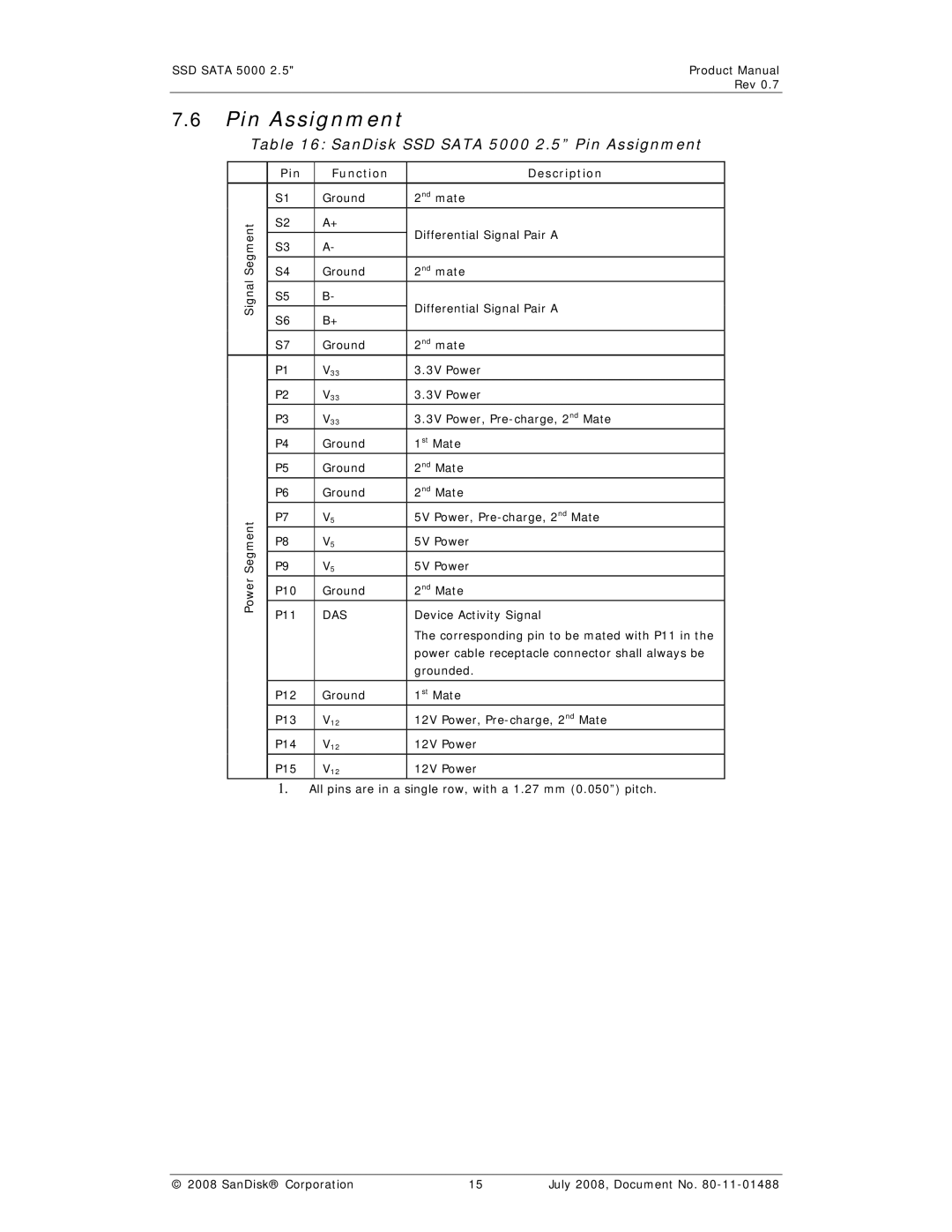
Table 16: SanDisk SSD SATA 5000 2.5” Pin Assignment
| Pin | Function | Description | |
| S1 | Ground | 2nd mate | |
Segment | S2 | A+ | Differential Signal Pair A | |
|
| |||
S3 | A- | |||
| ||||
|
|
| ||
S4 | Ground | 2nd mate | ||
Signal |
|
|
| |
S5 | B- | Differential Signal Pair A | ||
|
| |||
S6 | B+ | |||
|
| |||
|
|
|
| |
| S7 | Ground | 2nd mate | |
| P1 | V33 | 3.3V Power | |
| P2 | V33 | 3.3V Power | |
| P3 | V33 | 3.3V Power, | |
| P4 | Ground | 1st Mate | |
| P5 | Ground | 2nd Mate | |
| P6 | Ground | 2nd Mate | |
Segment | P7 | V5 | 5V Power, | |
P8 | V5 | 5V Power | ||
P9 | V5 | 5V Power | ||
Power | P10 | Ground | 2nd Mate | |
P11 | DAS | Device Activity Signal | ||
| ||||
|
|
| The corresponding pin to be mated with P11 in the | |
|
|
| power cable receptacle connector shall always be | |
|
|
| grounded. | |
|
|
|
| |
| P12 | Ground | 1st Mate | |
| P13 | V12 | 12V Power, | |
| P14 | V12 | 12V Power | |
| P15 | V12 | 12V Power | |
|
|
|
|
1.All pins are in a single row, with a 1.27 mm (0.050”) pitch.
© 2008 SanDisk® Corporation | 15 | July 2008, Document No. |
