Step 3: Add the Vise Assemblies to the Monitor Brackets:
Note: Do not overtighten the
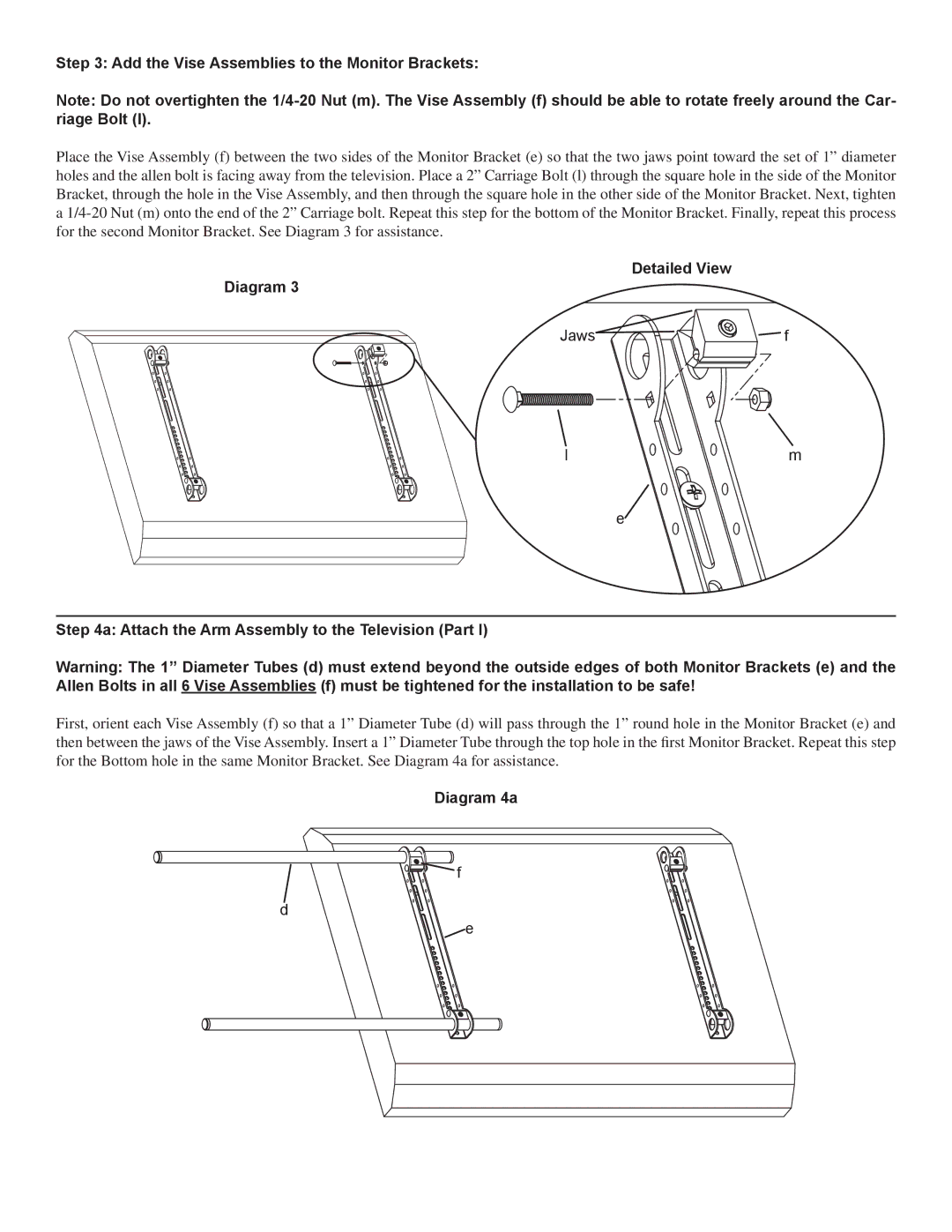
Place the Vise Assembly (f) between the two sides of the Monitor Bracket (e) so that the two jaws point toward the set of 1” diameter holes and the allen bolt is facing away from the television. Place a 2” Carriage Bolt (l) through the square hole in the side of the Monitor Bracket, through the hole in the Vise Assembly, and then through the square hole in the other side of the Monitor Bracket. Next, tighten a
Detailed View
Diagram 3
Jaws | f |
l | m |
e![]()
Step 4a: Attach the Arm Assembly to the Television (Part I)
Warning: The 1” Diameter Tubes (d) must extend beyond the outside edges of both Monitor Brackets (e) and the Allen Bolts in all 6 Vise Assemblies (f) must be tightened for the installation to be safe!
First, orient each Vise Assembly (f) so that a 1” Diameter Tube (d) will pass through the 1” round hole in the Monitor Bracket (e) and then between the jaws of the Vise Assembly. Insert a 1” Diameter Tube through the top hole in the first Monitor Bracket. Repeat this step for the Bottom hole in the same Monitor Bracket. See Diagram 4a for assistance.
Diagram 4a
![]() f
f
d
![]() e
e