Step 6: Hang the assembly onto the Wall Plate
Warning: This step may require 2 people to lift the assembly onto the Wall Plate! Sanus is not responsible for injury or damage.
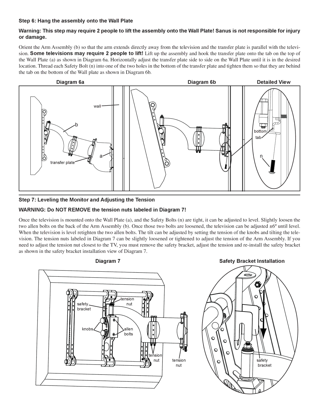
Orient the Arm Assembly (b) so that the arm extends directly away from the television and the transfer plate is parallel with the televi- sion. Some televisions may require 2 people to lift! Lift up the assembly and hook the transfer plate onto the tab on the top of the Wall Plate (a) as shown in Diagram 6a. Horizontally adjust the transfer plate side to side on the Wall Plate until it is in the desired location. Thread each Safety Bolt (n) into one of the two holes in the bottom of the transfer plate and tighten them so that they are behind the tab on the bottom of the Wall plate as shown in Diagram 6b.
Diagram 6a | Diagram 6b | Detailed View |
wall |
|
|
b |
|
|
|
| bottom |
|
| tab |
a |
| n |
transfer plate |
|
|
Step 7: Leveling the Monitor and Adjusting the Tension
WARNING: Do NOT REMOVE the tension nuts labeled in Diagram 7!
Once the television is mounted onto the Wall Plate (a), and the Safety Bolts (n) are tight, it can be adjusted to level. Slightly loosen the two allen bolts on the back of the Arm Assembly (b). Once those two bolts are loosened, the television can be adjusted ±6º until level. When the television is level retighten the two allen bolts. The tilt can be adjusted by setting the tension of the knobs and tilting the tele- vision. The tension nuts labeled in Diagram 7 can be slightly loosened or tightened to adjust the tension of the Arm Assembly. If you need to adjust the tension nut closest to the TV, you must remove the safety bracket, adjust the tension and
Diagram 7 | Safety Bracket Installation |
tension
safetynut bracket
knobs![]()
![]() allen bolts
allen bolts
tension |
|
|
nut | tension | safety |
| nut | bracket |