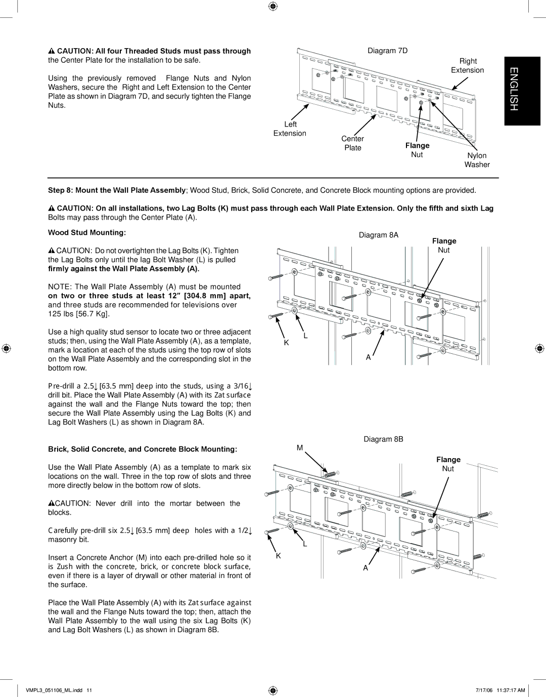
CAUTION: All four Threaded Studs must pass through |
| Diagram 7D |
| |
the Center Plate for the installation to be safe. |
|
| Right | |
Using the previously | removed Flange Nuts and Nylon |
|
| Extension |
|
|
| ||
Washers, secure the | Right and Left Extension to the Center |
|
|
|
Plate as shown in Diagram 7D, and securly tighten the Flange |
|
|
| |
Nuts. |
|
|
|
|
| Left |
|
|
|
| Extension | Center |
|
|
|
| Flange |
| |
|
| Plate | Nylon | |
|
|
| Nut | |
Washer
Step 8: Mount the Wall Plate Assembly; Wood Stud, Brick, Solid Concrete, and Concrete Block mounting options are provided.
![]() CAUTION: On all installations, two Lag Bolts (K) must pass through each Wall Plate Extension. Only the fifth and sixth Lag Bolts may pass through the Center Plate (A).
CAUTION: On all installations, two Lag Bolts (K) must pass through each Wall Plate Extension. Only the fifth and sixth Lag Bolts may pass through the Center Plate (A).
Wood Stud Mounting: | Diagram 8A | Flange |
|
| |
CAUTION: Do not overtighten the Lag Bolts (K). Tighten |
| Nut |
the Lag Bolts only until the lag Bolt Washer (L) is pulled |
|
|
firmly against the Wall Plate Assembly (A). |
|
|
NOTE: The Wall Plate Assembly (A) must be mounted on two or three studs at least 12″ [304.8 mm] apart, and three studs are recommended for televisions over 125 lbs [56.7 Kg].
Use a high quality stud sensor to locate two or three adjacent | L | |
studs; then, using the Wall Plate Assembly (A), as a template, | ||
K | ||
mark a location at each of the studs using the top row of slots | A | |
on the Wall Plate Assembly and the corresponding slot in the | ||
bottom row. |
|
ENGLISH
Brick, Solid Concrete, and Concrete Block Mounting:
Use the Wall Plate Assembly (A) as a template to mark six locations on the wall. Three in the top row of slots and three more directly below in the bottom row of slots.
![]() CAUTION: Never drill into the mortar between the blocks.
CAUTION: Never drill into the mortar between the blocks.
Carefully
Insert a Concrete Anchor (M) into each
Place the Wall Plate Assembly (A) with its flat surface against the wall and the Flange Nuts toward the top; then, attach the Wall Plate Assembly to the wall using the six Lag Bolts (K) and Lag Bolt Washers (L) as shown in Diagram 8B.
Diagram 8B
M
Flange
Nut
L
K
A
VMPL3_051106_ML.indd 11
7/17/06 11:37:17 AM