
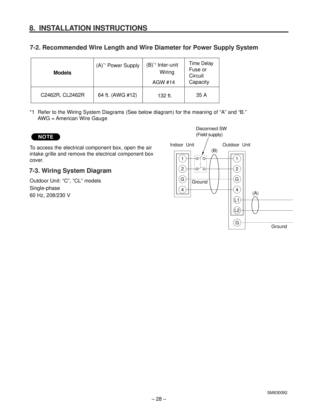
C2462R, CL2462R specifications
The Sanyo CL2462R and C2462R are versatile and innovative air conditioning models designed to meet the demands of residential and commercial spaces. Known for their advanced features, energy efficiency, and user-friendly operation, these units have garnered a reputation for reliability and performance.One of the standout features of the Sanyo CL2462R and C2462R is their energy efficiency. Equipped with inverter technology, these models adjust their cooling output based on the ambient temperature, minimizing energy consumption while maintaining consistent comfort levels. This not only helps in reducing electricity bills but also contributes to environmental sustainability, making them an attractive choice for the eco-conscious consumer.
Both models come with a powerful cooling capacity, ensuring rapid temperature reduction even in the most demanding conditions. The CL2462R features a robust compressor that provides an efficient cooling experience, while the C2462R balances power with refined performance, tailoring its output to the specific needs of the space it serves.
Another significant characteristic is their whisper-quiet operation. The Sanyo CL2462R and C2462R are designed with noise reduction technology, allowing them to operate at lower decibel levels. This feature makes them ideal for use in bedrooms, offices, or any quiet environment where disruption needs to be minimized.
User-centric design is prevalent in these models, with intuitive remote controls and programmable timers that allow users to customize their cooling experience. Both units feature multiple fan speeds, allowing users to choose their desired airflow levels for optimal comfort. Additionally, the units are equipped with air purification technologies, including filters that effectively trap dust, allergens, and pollutants, ensuring that the air circulated is clean and healthy.
The Sanyo CL2462R and C2462R also boast sleek designs that can complement various interior decor styles. Their compact dimensions make them easy to install without occupying too much space, making them a practical choice for modern living.
In summary, the Sanyo CL2462R and C2462R deliver exceptional performance, energy efficiency, and user-friendly features, making them ideal solutions for effective cooling. These models embody Sanyo's commitment to quality and innovation, providing consumers with reliable products that enhance comfort and improve air quality in any environment.