ELECTRICAL CONNECTIONS
WIRING
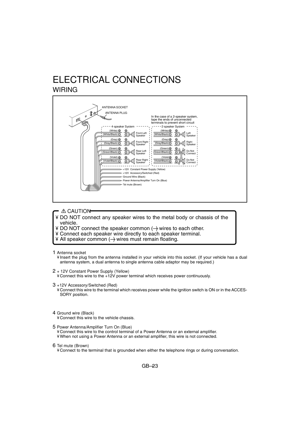
ANTENNA SOCKET
ANTENNA PLUG
4-speaker System
(White)
(White/Black)Front Left Speaker
(Gray)
(Gray/Black)Front Right Speaker
(Green)
(Green/Black)Rear Left Speaker
(Violet) | Rear Right | |
(Violet/Black) | ||
Speaker | ||
|
In the case of a
(White)
(White/Black)Left Speaker
(Gray)
(Gray/Black)Right Speaker
(Green)
(Green/Black) | Do Not | |
Connect | ||
| ||
(Violet | Do Not | |
(Violet/Black) | ||
Connect | ||
|
+12V Constant Power Supply (Yellow)
+12V Accessory/Switched (Red)
Ground Wire (Black)
Power Antenna/Amplifier Turn On (Blue)
![]() Tel mute (Brown)
Tel mute (Brown)
![]() CAUTION
CAUTION
•DO NOT connect any speaker wires to the metal body or chassis of the vehicle.
•DO NOT connect the speaker common
•Connect each speaker wire directly to each speaker terminal.
•All speaker common
1Antenna socket
•Insert the plug from the antenna installed in your vehicle into this socket. (If your vehicle has a dual antenna system, a dual antenna to single antenna cable adaptor may be required.)
2+ 12V Constant Power Supply (Yellow)
•Connect this wire to the +12V power terminal which receives power continuously.
3+12V Accessory/Switched (Red)
•Connect this wire to the terminal which receives power while the ignition switch is ON or in the ACCES- SORY position.
4Ground wire (Black)
•Connect this wire to the vehicle chassis.
5Power Antenna/Amplifier Turn On (Blue)
•Connect this wire to the control terminal of a Power Antenna or an external amplifier.
•When not using a Power Antenna or an external amplifier, this wire is not connected.
6Tel mute (Brown)
•Connect to the terminal that is grounded when either the telephone rings or during conversation.