Installation
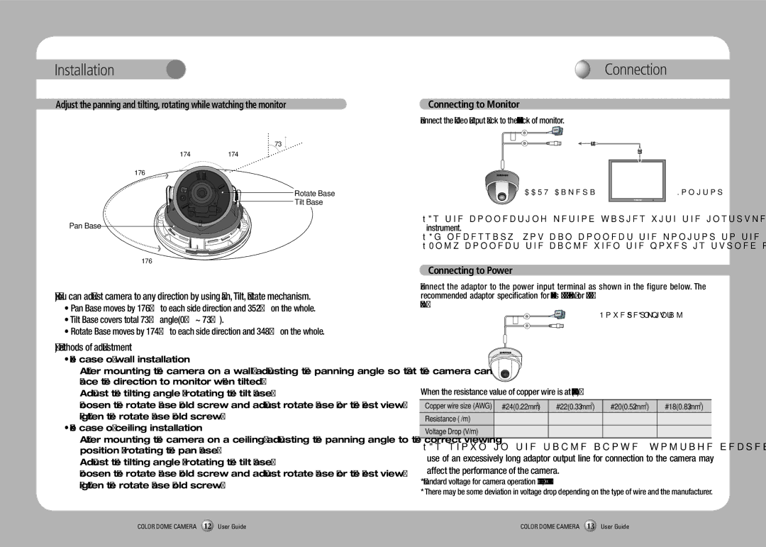
Adjust the panning and tilting, rotating while watching the monitor
73˚
174˚174˚
176˚
Rotate Base
Tilt Base
Pan Base
176˚
1)You can adjust camera to any direction by using Pan, Tilt, Rotate mechanism.
•Pan Base moves by 176˚ to each side direction and 352˚ on the whole.
•Tilt Base covers total 73˚ angle(0˚ ~ 73˚).
•Rotate Base moves by 174° to each side direction and 348° on the whole.
2)Methods of adjustment
•The case of wall installation
1After mounting the camera on a wall, adjusting the panning angle so that the camera can face the direction to monitor when tilted.
2Adjust the tilting angle by rotating the tilt base.
3Loosen the rotate base hold screw and adjust rotate base for the best view.
4 Tighten the rotate base hold screw.
•The case of ceiling installation
1 After mounting the camera on a ceiling, adjusting the panning angle to the correct viewing position by rotating the pan base.
2 Adjust the tilting angle by rotating the tilt base.
3Loosen the rotate base hold screw and adjust rotate base for the best view.
4Tighten the rotate base hold screw.
Connection
Connecting to Monitor
Connect the Video Output jack to the
CCTV Camera |
| Monitor |
| ||
|
|
|
|
|
|
•As the connecting method varies with the instruments, refer to the manual supplied with the instrument.
•If necessary, you can connect the monitor to the REMOTE jack on the back of your camera.
•Only connect the cable when the power is turned off.
Connecting to Power
Connect the adaptor to the power input terminal as shown in the figure below. The recommended adaptor specification for
When the resistance value of copper wire is at [20˚C(68˚F)]
Copper wire size (AWG) | #24(0.22mm2) | #22(0.33mm2) | #20(0.52mm2) | #18(0.83mm2) |
Resistance (Ω/m) | 0.078 | 0.050 | 0.030 | 0.018 |
Voltage Drop (V/m) | 0.028 | 0.018 | 0.011 | 0.006 |
|
|
|
|
|
•As shown in the table above, voltage decreases as the wire gets longer. Therefore use of an excessively long adaptor output line for connection to the camera may
affect the performance of the camera.
*Standard voltage for camera operation : DC 12V ± 10%, AC 24V ±10%
*There may be some deviation in voltage drop depending on the type of wire and the manufacturer.
COLOR DOME CAMERA 12 User Guide | COLOR DOME CAMERA 13 User Guide |