Connection
Notes
•Be sure to connect power only after all the installation is complete.
•Note that AC / DC adaptor is not supplied with camera.
•Ground should be connected to the GND terminal.
Operating Your Camera
Menu Configuration
MAIN SETUP
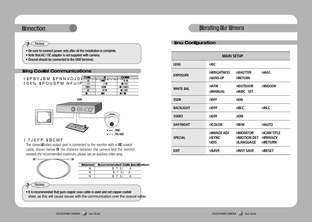
Using Coaxial Communications
•Coaxial Communications System
•OSD Control method
CAMERA | DVR | CONTROLLER |
SET | MENU/ENTER | OSD KEY |
UP | UP KEY | JOYSTICK UP |
DOWN | DOWN KEY | JOYSTICK DOWN |
LEFT | LEFT KEY | JOYSTICK LEFT |
RIGHT | RIGHT KEY | JOYSTICK RIGHT |
LENS | ●DC |
|
|
|
|
|
|
EXPOSURE | ●BRIGHTNESS | ●SHUTTER | ●AGC |
●RETURN |
| ||
|
| ||
|
|
|
|
WHITE BAL | ●ATW | ●OUTDOOR | ●INDOOR |
●MANUAL | ●AWC→SET |
| |
|
|
DVR
DVD
• |
| : BNC |
| ||
• | ||
• Video Cable
The camera's video output port is connected to the monitor with a BNC coaxial cable, shown below : If the distance between the camera and the monitor exceeds the recommended maximum, please use an auxiliary video amp.
Distance | Recommended Cable Specification |
300m | |
450m | |
600m |
Notes
•It is recommended that pure copper coax cable is used and not copper coated steel, as this will cause issues with the communication over the coaxial cable.
SSDR | ●OFF | ●ON |
|
|
|
|
|
BACKLIGHT | ●OFF | ●BLC | ●HLC |
|
|
|
|
SSNR3 | ●OFF | ●ON |
|
|
|
|
|
DAY/NIGHT | ●COLOR | ●B/W | ●AUTO |
|
|
|
|
| ●IMAGE ADJ | ●MONITOR | ●CAM TITLE |
SPECIAL | ●SYNC | ●MOTION DET | ●PRIVACY |
| ●DIS | ●LANGUAGE | ●RETURN |
|
|
|
|
EXIT | ●SAVE | ●NOT SAVE | ●RESET |
|
|
|
|
COLOR DOME CAMERA 14 User Guide | COLOR DOME CAMERA 15 User Guide |