INSTALLATION INSTRUCTIONS
IMPORTANT | • In order to install this wired remote controller onto a | |
|
• Once the wired remote controller is connected, the wireless remote controller cannot be used.
■Parts supplied with the remote controller
See Table 1.
■Remote controller installation guidelines
Installation location
•Mount the remote controller 3.3 to 4.9 ft. (1 to 1.5 meters) off the floor where it can sense the average temperature of the room.
•Do not mount the remote controller in a place exposed to direct sunlight or where it is exposed to outside air such as near a window.
•Do not mount the remote controller behind a curtain or other object so that it is separated from the air circula- tion of the room.
•Mount the remote controller inside the room being air conditioned.
Switching the room temperature sensor
Table 1
Parts |
| Figure | Q'ty | Parts | Figure | Q'ty | |
Wired |
|
|
|
|
| 26.2 ft. (8m) |
|
|
|
|
| Wire |
|
| |
remote |
|
|
| 1 |
| 1 | |
|
|
| harness |
| |||
controller |
|
|
|
|
|
| |
|
|
|
|
|
|
| |
Machine | 5/32 | 15/16" |
| Instruction |
|
| |
(4 | 25mm) | 2 |
| 1 | |||
screws |
|
|
| manual |
| ||
|
|
|
|
|
| ||
| 5/32 | 15/16" |
|
|
|
| |
Tapping | (4 | 25mm) | 2 | Installation |
| 1 | |
screws |
|
|
| Instructions |
| ||
|
|
|
|
|
| ||
Spacers | 2 |
Room temperature sensors are separately incorporated in both the indoor unit and the remote controller. Either sensor can be used to sense the room temperature. The indoor unit sensor is usually used.
If you wish the remote controller to sense the room temperature, press the SENSOR button with a ballpoint pen or tool with a small tip. (Refer to Fig. 9 on page 4 to locate the SENSOR button.)
■ How to install the remote controller
IMPORTANT
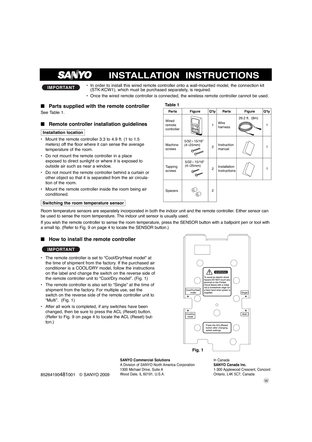
• The remote controller is set to “Cool/Dry/Heat model” at the time of shipment from the factory. If the purchased air conditioner is a COOL/DRY model, follow the instructions on the label and change the switch on the reverse side of the remote controller unit to “Cool/Dry model”. (Fig. 1)
• The remote controller is also set to “Single” at the time of shipment from the factory. For multiple use, set the switch on the reverse side of the remote controller unit to “Multi”. (Fig. 1)
• After all work is completed, if any switches have been changed, then be sure to press the ACL (Reset) button. (Refer to Fig. 9 on page 4 to locate the ACL (Reset) but- ton.)
| Fig. 1 |
|
|
|
|
|
|
|
|
| |
|
|
|
|
| |
| SANYO Commercial Solutions | In Canada | |||
| A Division of SANYO North America Corporation | SANYO Canada Inc. | |||
85264190481001 © SANYO 2009 | 1300 Michael Drive, Suite A | ||||
Wood Dale, IL 60191, U.S.A. | Ontario, L4K 5C7, Canada | ||||
|
|
|
|
| W |