PARTS NAMES
1
13
2 4
2
3![]()
![]()
4
5
12![]() 3
3 ![]() 2
2
1
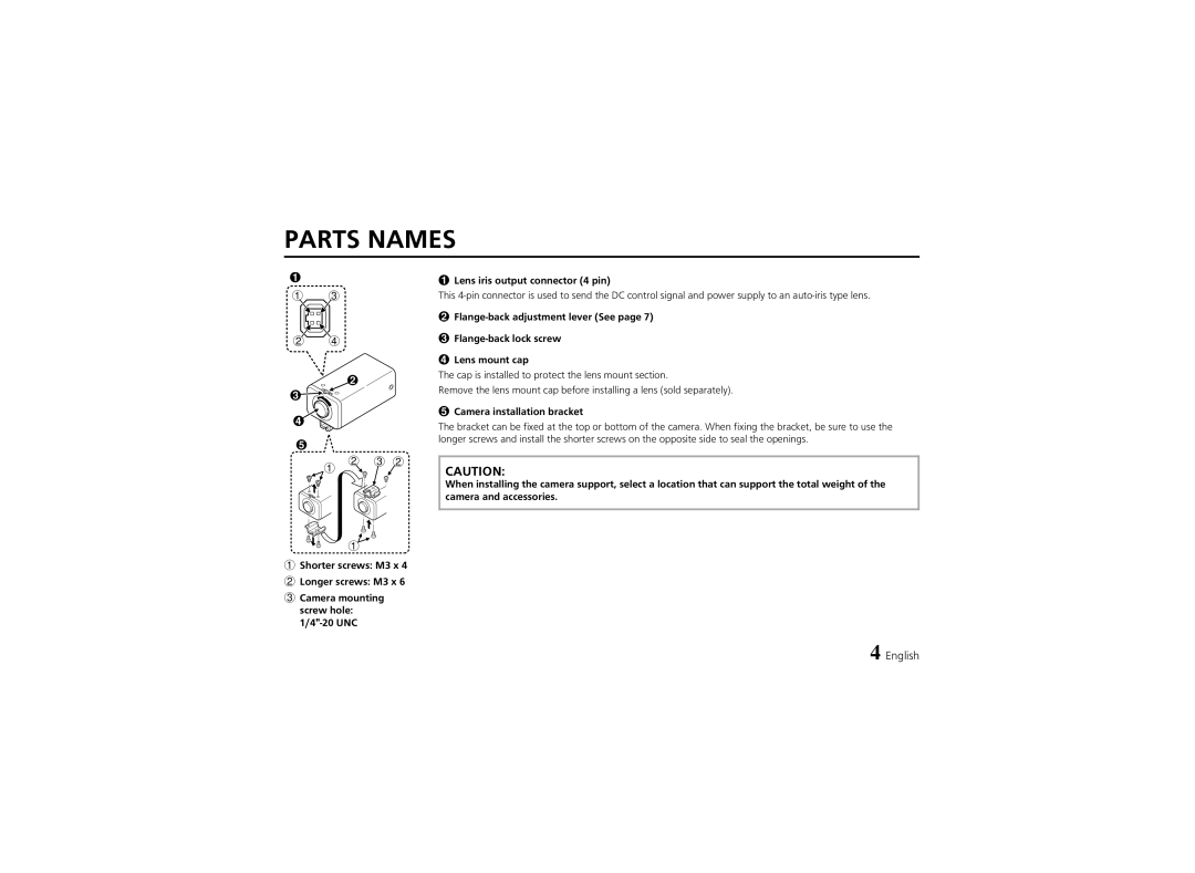
1Shorter screws: M3 x 4
2Longer screws: M3 x 6
3Camera mounting screw hole:
1Lens iris output connector (4 pin)
This
2
3
4Lens mount cap
The cap is installed to protect the lens mount section.
Remove the lens mount cap before installing a lens (sold separately).
5Camera installation bracket
The bracket can be fixed at the top or bottom of the camera. When fixing the bracket, be sure to use the longer screws and install the shorter screws on the opposite side to seal the openings.
CAUTION:
When installing the camera support, select a location that can support the total weight of the camera and accessories.
4 English