OPERATOR’S Manual
STT61V-31EFI-SS
With a serial number E3700001 to E3799999
STT-31EFI-SS
Table of Contents
Following Section
Adjustments
Direction Reference
USE only Scag Approved Attachments and Accessories
General Information
Introduction
Symbols
Symbol Description
STT Models
Signal Word
Safety Information
Signal Words
This symbol means Attention! Become Alert! Your
Operation Considerations
Section
Foldable Roll-over protection system if equipped
Roll-Over Protection System
Foldable Roll-Over Protection System
Using a spark arrestor
Maintenance Considerations & Storage
Safety And Instructional Decals Install Belt COvER Before
Electrical
Specifications
Power Head
Engine
Weights And Dimensions
Cutter Deck
Hydraulic System
Controls And Instrument Identification
Operating Instructions
Dump Valve Control
Safety Interlock System
Forward Travel
Initial Run-In Procedures
Starting The Engine
Ground Travel And Steering
Reverse Travel
Engaging The Deck Drive Cutter Blades
Removing Clogged Material
Hillside Operation
Parking The Mower
After Operation
Adjusting Cutting Height
Moving Mower With Engine Stopped
Recommendations For Mowing
Adjusting The Height Adjust Pedal
Adjusting The Steering Levers
Towing Optional Hitch Accessory
Condition Cause Cure
Troubleshooting Cutting Conditions
Sloping Ridge Across
E v e n C u t o n F l at
Ground Wavy High-Low Appearance, Scalloped
Cut, or Rough Contour
Cutting path
Scalping Blades Hitting
Dirt or CuttingVery Close To the Ground
Step Cut Ridge in Center
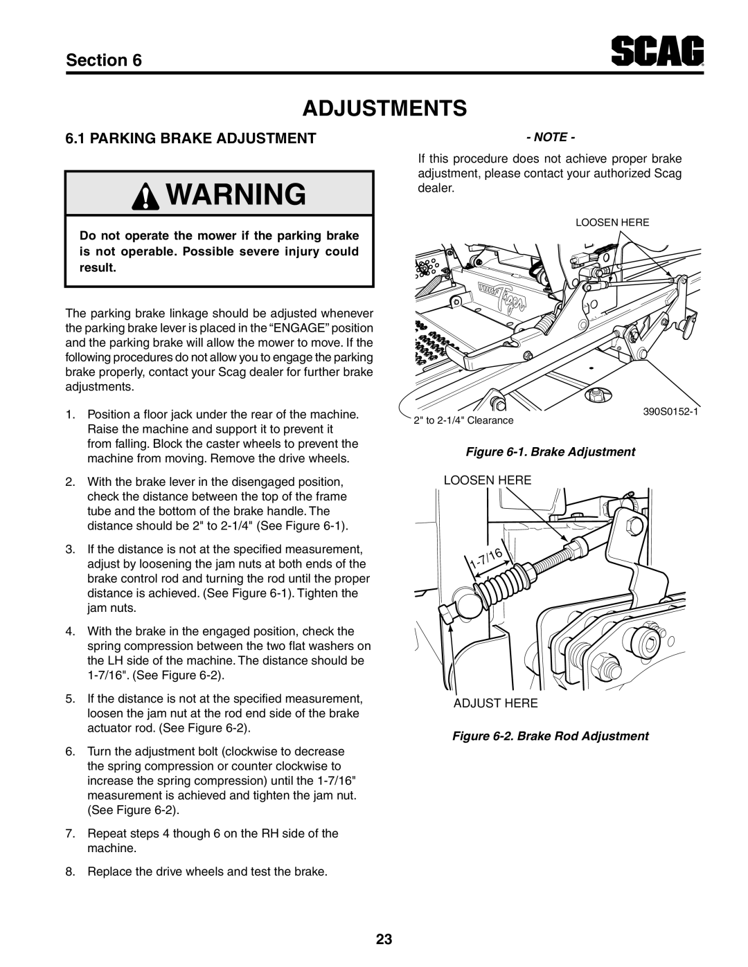
Brake Adjustment
Adjustments
RH Steering Control Rod Adjustment
Neutral Adjustment
Tracking Adjustment
Throttle Control and Choke Adjustments
Cutter Deck Pitch
Cutter Deck Level
Cutter Deck Height
Cutter Deck Height Adjustment
Custom-Cut Baffle Adjustment
Position Custom-Cut Baffle Adjustment Early Models
Position Custom-Cut Baffle Adjustment Current Production
Position Custom-Cut Baffle Adjustment
Clutch Air Gap Adjustment
Electric clutch adjustment
Hours
Maintenance
Maintenance Chart Recommended Service Intervals
Procedure Comments Break-In 100 200 500 First
Location Lubrication Interval Lubricant NO. Places
Lubrication
Lubrication Fitting Points
Changing Hydraulic Oil
Checking Hydraulic Oil Level
Engine Fuel System
Engine Oil
Engine Air Cleaner
Cleaning and/or Replacing Air Cleaner Element
Replacing In-Line Fuel Filter Elements
Jump Starting
Battery
Charging the Battery
Battery Electrolyte First AID
Blade Inspection
Blade Replacement
Drive Belts
Cutter Blades
Tires
Cutter Deck Gearbox
Checking Lubricant Level
Checking Coolant Level
Cleaning the Radiator Debris Screen
Cooling System
Changing Lubricant
Checking The Fan Belt Tension
Body, Deck, And Upholstery
Scag Approved Attachments And Accessories
Illustrated Parts List
Illustrated Parts List
61V & 72VS Cutter Decks
Description
Cutter Deck Controls
Cutter Deck Controls
Sheet Metal Components
Fender Weldment, RH Bolt, Hex Hd., 5/16-18 x 1, Zinc 43606
STT ROLL-OVER Protection System with Suspension Seat
STT ROLL-OVER Protection System with Suspension Seat
Deck Drive Components
Belt Guard, Rear Hinge, Belt Guard 481309 Latch, Hood 482845
Engine & Attaching Parts 31HP-EFI Kohler
Available through the individual engine manufacturer
Brake and Steering Components
Grip, Handle Bar
Fuel and Hydraulic System Kohler 31EFI
24 403
BDP-16A Hydraulic Pump Assembly with Cooling FAN
HG70924 Charge Pump Kit .19 STD. Splined HG51457
Electrical System 31HP-EFI Kohler
Electrical System 31HP-EFI Kohler
Heavy-Duty Commercial
STT-EFI Decals Page2
Electrical Schematic Kohler 31HP EFI
Limited Warranty Commercial Equipment
Garantía Limitada Equipo Comercial
Nota
Tapicería y plataforma Cuerpo
Radiador del desechos de criba la de Limpieza .B
Ventilador del correa la de tensión la de Verificación .C
La de cambios de Caja
Refrigeración de Sistema
Corte de plataforma
Corte de cuchillas con trabajar al ojos y
Llantas
Cuchilla la de Reemplazo .C
Nota Cuchilla la de Reemplazo .8-7 Figura
Puente por Arranque .B
Corte de Cuchillas
Transmisión de Correas
Cuchilla la de Inspección .A
Batería DE Electrolito Para Auxilios Primeros
Batería
Batería la de Carga .A
Agua con Enjuague externo Contacto
Del elementos los de Reemplazo .B
Motor del aire de Filtro
Aire de filtro del elemento del reemplazo y/o Limpieza .A
Línea en combustible de filtro
Motor del Aceite
Motor del combustible de Sistema
Hidráulico Sistema
Hidráulico aceite de nivel del Verificación .A
Hidráulico aceite de Filtro .3-7 Figura
Conexión de puntos de Lubricación .1-7 Figura
Lubricación
Ciones Lubricación Ubica Lubricante Ubicación DE Intervalo
Horas
Recomendados servicio de Intervalos mantenimiento de Tabla
Mantenimiento
Montaje de accesorios de Ubicación Montaje de Ranura
Personalizado corte de deflector del Ajuste
Posiciones 7 de personalizado corte de deflector del Ajuste
Posiciones 3 de personalizado corte de deflector del Ajuste
Plataforma la de altura de Ajuste .7-6 Figura
Corte de plataforma la de Altura
Corte de plataforma la de Tope .8-6 Figura
Corte de
Corte de plataforma la de Inclinación
Corte de plataforma la de Nivel
Corte de Plataforma la de nivel del Ajuste .5-6 Figura
Estrangulación y aceleración
De controles los de Ajustes
Alineación de Ajuste
Neutral Ajuste
Desplazamiento de Ajustes
Freno del vAjuste .1-6 Figura
Ajustes
Estacionamiento de freno del Ajuste
Freno de varilla la de Ajuste .2-6 Figura
Inclinado Corte
Corte de trayectoria
La de ancho del través
Inclinadas Crestas
Volado corte ondulada
La de ancho lo a
Inclinadas Salientes
Irregular perfil o
La en cortar sin césped
Corte de trayectorias
Entre cortar sin césped
De Franjas Vetas
Altura la de ajuste de pedal del Ubicaciones .8-4 Figura
Opcional enganche de accesorio Remolque
Plataforma la de liberación de Palanca .6-4 Figura
Altura de ajuste de pedal del Ajuste
Dirección de palancas las de Ajuste
Dirección De palancas las de Ajuste .7-4 Figura
Detenido motor el con cortacésped del Desplazamiento
Corte de altura la de Ajuste
Césped el
Cortar para Recomendaciones
Cuesta una en Operación
Atascado material del Retriro
Operación la de Después
Cortacésped del Estacionamiento
Del accionamiento de Interruptor .3-4 Figura
Corte de cuchillas plataforma de transmisión la de Conexión
Reversa en Desplazamiento
Cortador
Adelante hacia Desplazamiento
Dirección y terreno el en Desplazamiento
Motor del Arranque
Inicial arranque de Procedimientos
Usado .1-4 Figura dirección de derecho Control
Seguridad de bloqueo de Sistema
Descarga de válvula de Control .2-4 Figura
La Indica .1-4 Figura combustible de Indicador
Operación DE Instrucciones
Instrumentos e controles de Identificación
Instrumentos e Controles .1-4 Figura
Productividad
Dimensiones y Pesos
Motor
Especificaciones
Potencia de Cabezal
Eléctrico Sistema
Seguridad de y instructivas Calcomanías
REvErSA AdELAntE
Chispas de supresor un Utilice
Almacenamiento y mantenimiento
De Consideraciones
Muerte la o graves lesiones ocasionar
Mantener y inspeccionar de incumplimiento El
Vuelco contra protección de plegable Sistema .1-2 Figura
Vuelco contra protección de Sistema
Equipado viene si vuelco contra
Protección de Plegable Sistema
Peligro
Operación de Consideraciones
Señalización de Palabras
Seguridad DE
Información
Operación la a previas Consideraciones
Símbolos
STT Modelos
Descripción Símbolo
General Información
Instrucciones de Referencia
Scag POR Aprobados Dispositivos USE Sólo
Ajustes 6 Sección
Sección Sigue Comercial Equipo Limitada Garantía
List Parts Illustrated 8 Sección
Mantenimiento 7 Sección
General Información 1 Sección
Operación DE Instrucciones 4 Sección
Especificaciones 3 Sección
Seguridad DE Información 2 Sección
SS-31EFI-STT61V
72VS-SMT
61V-SMT
SS-31EFI-STT
Operador DEL Manual